What is Microcontroller?
How do microcontrollers accomplish that?
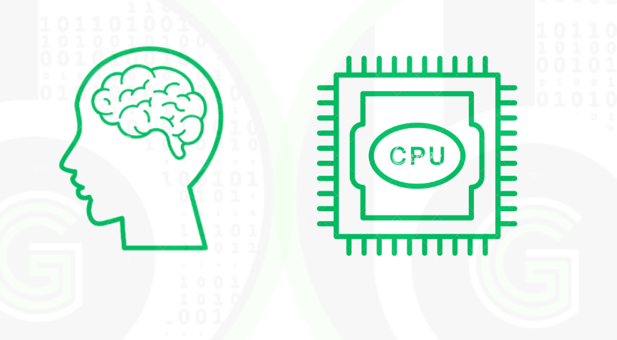
![]() Just like human beings have brain where processing of all data is done microcontrollers have CPU. In the CPU(Central Processing unit), all the processing of data, speed of execution is done. Thus CPU’s are the brain of the microcontrollers. Often the word CPU is used interchangeably with processor/core.
Just like human beings have brain where processing of all data is done microcontrollers have CPU. In the CPU(Central Processing unit), all the processing of data, speed of execution is done. Thus CPU’s are the brain of the microcontrollers. Often the word CPU is used interchangeably with processor/core.
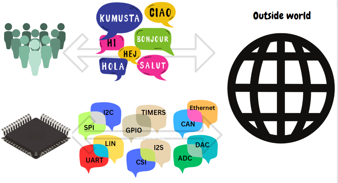
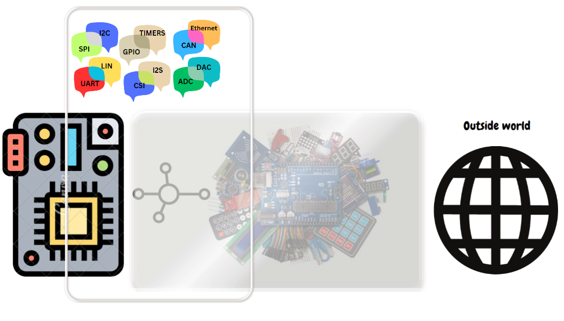
![]() Just like human beings use some form of language to communicate with outside world like English, Spanish, Hindi and etc. Same way microcontrollers use different communication protocols (UART, I2C, SPI, CAN, LIN, cryptography, I2S, CSI 1-wire, and many other) and digital/analog signals(GPIO, PWM, ADC, DAC, TIMERS) to communicate with the outside world.
Just like human beings use some form of language to communicate with outside world like English, Spanish, Hindi and etc. Same way microcontrollers use different communication protocols (UART, I2C, SPI, CAN, LIN, cryptography, I2S, CSI 1-wire, and many other) and digital/analog signals(GPIO, PWM, ADC, DAC, TIMERS) to communicate with the outside world.
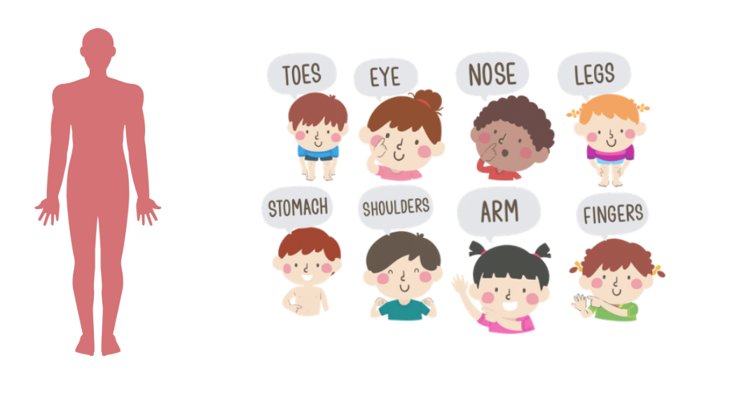
![]() Just like human beings have different body parts to interact with outside world, microcontrollers have different peripherals which are used to interact with outside world. For each Communication Protocol and digital/analog signals that are stated above there is some corresponding peripheral in microcontrollers.
Just like human beings have different body parts to interact with outside world, microcontrollers have different peripherals which are used to interact with outside world. For each Communication Protocol and digital/analog signals that are stated above there is some corresponding peripheral in microcontrollers.
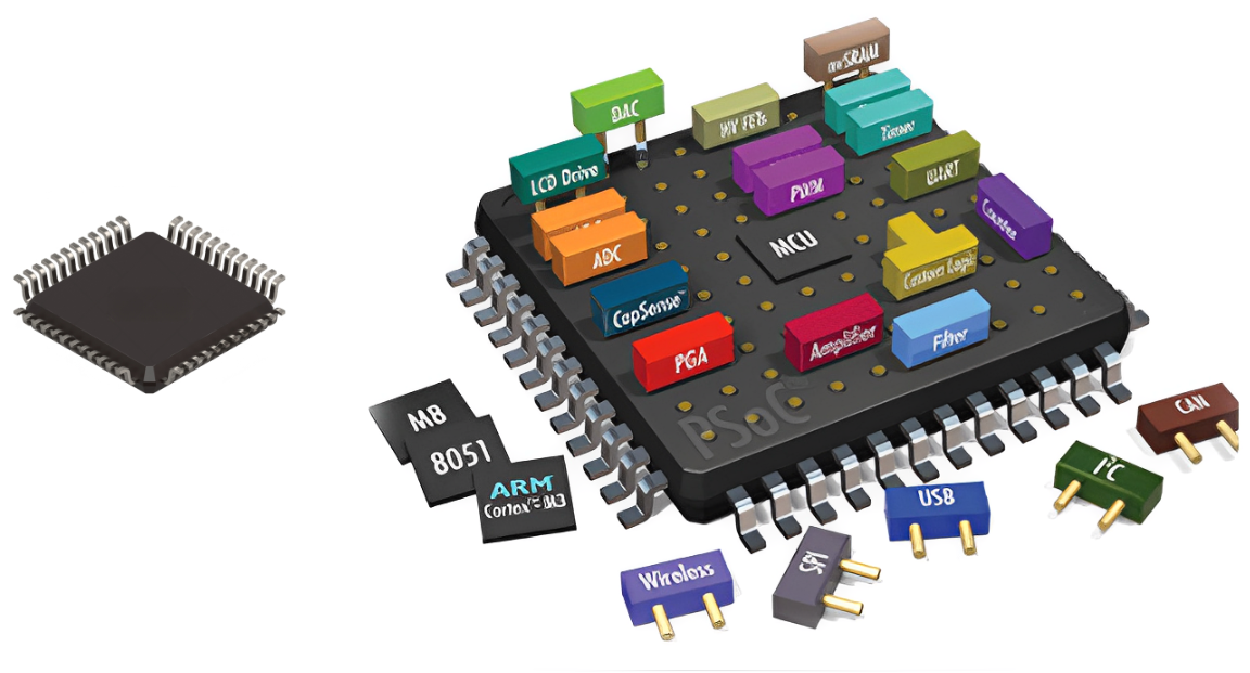
![]() Just like in human being’s brain sends signals to body parts, same way in microcontroller for using peripherals some configurations and programming has to be done to use them, this is called peripheral coding/drivers. That would be explaining in below sections.
Just like in human being’s brain sends signals to body parts, same way in microcontroller for using peripherals some configurations and programming has to be done to use them, this is called peripheral coding/drivers. That would be explaining in below sections.
![]() Now some sensors and modules are connected to Microcontrollers as an intermediate between the outside world and microcontrollers. And these sensors and modules communicate with specified communication protocols.
Now some sensors and modules are connected to Microcontrollers as an intermediate between the outside world and microcontrollers. And these sensors and modules communicate with specified communication protocols.

Microcontrollers are connected to different sensors and modules according to the industry in which they are being used. Microcontrollers communicate with these sensors and modules by some communication protocol via the peripherals of the MCU. Sensor and modules act as an intermediate between the microcontrollers and world, to get information from the outside world that is input to the microcontrollers(input). Then this data is processed and analyzed by the CPU (brain of MCU), where all these calculations, processing, operations are done. And then information is sent from the microcontrollers(output) to corresponding sensors and modules to show results or control the outside world. And That’s how microcontrollers can be used to make any electronic gadget of any Industry.
- Wearable Technology: Microcontrollers are used for development of smart watches. Microcontroller is connected with different sensor/modules like RTC3231 for time monitoring, heart rate sensor, oxygen sensor for checking body vitals, screen display, Wi-Fi/ BLE module for connectivity, 3-D accelerometer sensor for step counting(pedometer). Now these devices communicate with microcontroller via some communication protocol via the peripheral of the MCU.
- Time monitoring(RTC3231) communicates via I2C protocol, so it is connected to MCU via I2C peripheral.
- Heart Rate sensor (SEN-11574/AD8232) communicates via analog signal, so it is connected to MCU via ADC peripheral.
- oxygen sensor (MAX30100) communicates via I2C protocol, so it is connected to MCU via I2C peripherals.
- OLED screen display(SSD1306) communicates via SPI protocol, so it is connected to MCU via SPI peripheral.
- Wifi/BLE module communicates via UART protocol, so it is connected to MCU via UART peripheral.
- 3-D accelerometer (LSM303D) communicates via I2C protocol, so it is connected to MCU via I2C peripheral.

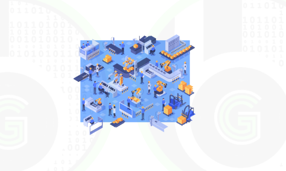
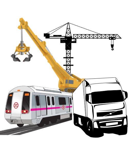
- Industrial Automation (Smart Energy meter): Microcontrollers are used in development of Smart energy meters. Microcontroller is connected to sensor/module like HLW8012 for AC Power measurement, INA219 for DC Power measurement, Wifi/BLE module for IoT connectivity, RS232 industrial communication support, SD-Card for data recording/storage. Now these devices communicate with microcontroller via some communication protocol via the peripheral of the MCU. Like
- AC Power measurement sensor (HLW8012) communicates via Digital PWM signals, so it is connected to MCU via Timer peripheral.
- DC Power measurement sensor(INA219) communicates via I2C protocol, so it is connected to MCU via I2C peripheral.
- Data Recording/Storage( SD card module, W25Q flash memory) communicates via SPI protocol, so it is connected to MCU via SPI peripheral.
- OLED screen display(SSD1306) communicates via SPI protocol, so it is connected to MCU via SPI peripheral.
- Wi-Fi/BLE module communicates via UART protocol, so it is connected to MCU via UART peripheral.
- RS232 is done using UART protocol, so it is connected via UART peripheral.

- Automotive: use of microcontrollers in automotive industry is immense now days. hundreds of MCU are used in a car. To give idea of one such example is electric immoblizer. To explain in simple way. Electric immoblizer is an electronic device used in automotive. It switches on the engine of car, only if electronic authenticated key is used to on the car. For this functionality, RFID tags are used in car keys. So electric immobilizer has broadly 2 sensor/modules. One RFID module like MFRC522 and a high voltage relay/optocoupler to on the engine of car via MCU. Now these devices communicate with microcontroller via some communication protocol via the peripheral of the MCU. Like
- RFID module (MFRC522) communicates via SPI protocol, so it is connected to MCU via SPI peripheral.
- Relay/Optocoupler communicates via digital On/OFF signals, so it is connected to MCU via GPIO peripheral.
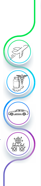
- Avionics: Drones are small aerial bots that are extensively used now days in avionics industry. For the development of Drones there is use of Microcontrollers. Microcontroller is connected to sensor/Module like accelerometer sensors(ADXL345) for axis control of drone, barometric sensor((BMP280) for pressure & altitude measurement, Time of flight sensor(VL53L0X) used for distance mapping and 3D imaging technology, Camera sensor(IMX214) for capturing images and videos, Temperature sensor(DHT11) for monitoring temperature variations as drone flight high, GPS module(NEO-^m) for Drone tracking and GPS coordinates, RF transceiver chips(HM10) for Controlling drone via remote. Now these devices communicate with microcontroller via some communication protocol via the peripheral of the MCU. Like
- Accelerometer (ADXL345) accelerometer sensor can communicate via I2C and SPI protocol, so it is connected to MCU via either one peripheral (I2C or SPI).
- Barometric sensor (BMP280) communicates via I2C peripheral, so it is connected to MCU via I2C peripheral.
- Camera sensor (IMX214) communicates via CSI protocol, so it is connected to MCU via CSI peripheral.
- Temperature sensor (DHT11) communicates via one-wire digital protocol, so it is connected to Timer peripheral.
- GPS module (Neo 6M) communicates via UART protocol, so it is connected to UART peripheral.
- RF transceiver chips (HM10) communicates via SPI protocol, so it is connected via SPI peripheral.
t
 Microcontrollers are designed and developed by the Semiconductor Companies. These Companies designs the microcontrollers for different industries (listed above), where these microcontrollers are used for product development.
Semiconductor industry is multi-billion-dollar industry, companies are as big as google, amazon & Microsoft (some are even larger than that).
Name of Semiconductor companies:
- NXP Semiconductors
- Renesas Semiconductors
- STMicroelectronics
- Texas Instruments
- Nordic Semiconductors
- Silicon Labs
- Marvel Semiconductors
- Microchip
- Intel
- QUALCOMM
- AMD Semiconductors
- ARM Processor
- Nvidia
- Analog Devices
Semiconductor companies not only designs and develop the microcontrollers but instead many other electronic/integrated chips (ASICS, memory chips, sensor chips, IoT chips, discreate electronics, development boards and etc.)Apart from just electronic chips, these companies develop the Software packages, Software Tools, Software Applications (ML, AI based), Hardware tools and also do Core RnD on the next upcoming technologies in the fields like of Automotive, IoT, Avionics, Industrial Automation and list will never end.

Designing of microcontrollers is done via VLSI/VHDL technology and then programming on those microcontrollers to build the applications is done via Embedded Software/Firmware Develpment.
To give a practical use case, you guys must have heard of Arduino. Well Arduino is a development, in which there is microcontroller Atmega 328. This microcontroller is designed and developed by Microchop technologies semiconductor company. Another is NodeMCU, which is also a development board, which has ESP8266 IoT MCU which is designed and developed by Espriff Systems. Most of the hobbyist and students are aware of only these 2 controllers, but there are number of other microcontrollers which are designed and developed. Like STM32 Blue Pill, is a development board which has STM32F103 MCU is ARM Core Based Microcontroller developed and designed by STMicroelectronics. Another is Teensy development boards which has I.MX1062 microcontrollers designed and developed by NXP semiconductors.
At the gettobyte, you are going to find content and tutorial series on different microcontrollers of different vendors. explaining how to use those Industrial microcontroller and tutorials on how to use the peripherals of Industrial microcontrollers to come out of Arduino environment. And get industry ready skills and knowledge in microcontroller field’s
Now like there are categorization in human beings in terms of color, features, gender kind of same way there are categorization in microcontroller in terms of:
- Which CPU architecture and CPU core is used (RISC-V, ARM, CISC, Power architecture, 8-bit architectures), every CPU architecture has some features and specs. Every human has unique brain and only 1 bran, but different microcontrollers can have same CPU core.
- Bit size of microcontroller (8/16/32 bit Microcontrollers), it’s kind of like amount of data that microcontroller can process. 32 bit can process more data and 8 bit would process less data.
- Then depending on peripherals support microcontroller has, more peripheral support it has a greater number of applications can be built from it by connecting different sensors/modules to it.
- Microcontroller’s has memory , as in the end we have to write some program to control the microcontroller, that program is written inside the microcontroller memory. So, amount of memory microcontrollers has (Flash Memory, RAM, SRAM and etc.), depending on that too there is categorizations in microcontroller.
- Support of Software Development Kit and Hardware Development kit for the corresponding microcontroller.
Okay, so lot has been talked about Microcontrollers. Now how to get started with it and in what chronology. Well Microcontroller technology is very vast and has many exciting/interesting topics. Best way to start learning about microcontrollers is by doing Embedded Software/Firmware Development.
From the Embedded Software/Firmware developer, below defined is the best way to start with the microcontrollers:
- Let’s, take MCU of some industry level vendor not Arduino/ESP Framework (let’s say NXP Semiconductors S32K144 MCU) and then get its development board: (ElecronicsV3). You can get the development board from this website: S32K144 Elecronics V3 with onboard J-Link, BNO055 and CAN – Electronics Infra
For NXP S32K144 MCU, buy this breadboard compatible eval board, its built on automotive MCU which will enable one to technologies which Arduino/ESP doesnt support. Get to know about Pinout and pins description of the MCU.
- And then setup is its SDK. So understand what Software Development Kit is, why is it needed. Software Development Kit comprises of IDE, code configuration tools, peripheral drivers and software debugging tools.
For NXP S32K144 MCU, Install the S32 Design Studio IDE, Freemaster debugging tool and software package of S32K1 for peripheral drivers(Real Time Drivers). Viewers can refer to S32 DS IDE getting starting blog, for getting to know
- After that understand the microcontroller architecture, the processor architecture of the MCU. Different kind of interrupts and faults in the MCU.
Reading the S32K144 Reference manual and Datasheet. First 2-3 chapters of both the docs and try to understand terminologies, keywords which are written, features and specs of S32K144.Then S32K144 MCU has ARM Cortex M4 architecture, so understanding, about ARM architecture and various components in it from its technical reference manual. Refer to this blog for S32K144 MCU understanding
- After that, understanding the basic peripherals and communication protocols of the MCU so that one can get to know how application build around MCU. Theoretical understanding of the communication protocol, digital/analog signals and then relating how is that theory being implemented in MCU by understating the peripheral drivers of that MCU. Every MCU vendor provide the peripheral driver for the corresponding MCU by the name of different names: Real Time drivers, Device drivers and etc. That too we are going to explore Autosar MCAL RTD, which is universal standard stack for using automotive MCU peripherals.
NXP S32K144 MCU has number of peripheral. NXP does provide peripheral drivers for the peripheral of the S32K144 MCU by the name of Real Time Drivers. I have written well formatted blogs on all the peripherals of s32K144 MCU by explaining the demo example of peripheral drivers, features of corresponding peripheral in MCU. Refer from here. At gettobyte you can find peripheral driver tutorial on number of Industrial controllers.
- Now connect different sensors & modules to corresponding peripheral and make the sensor/module run via microcontroller. In this we need to understand at first the working principal of that sensor/module and then understand from its datasheet about how to control that sensor/module via microcontroller so as to run it and then writing its device driver. Device driver is a program written to interface difference sensor/module with microcontroller.
Connect different type of sensor and modules to MCU. At gettobyte their are proper tutorial series on how to connect sensor/module with any MCU. Have connected number of different sensor/module to NXP S32K144 MCU. Refer to sensor and module section to start.