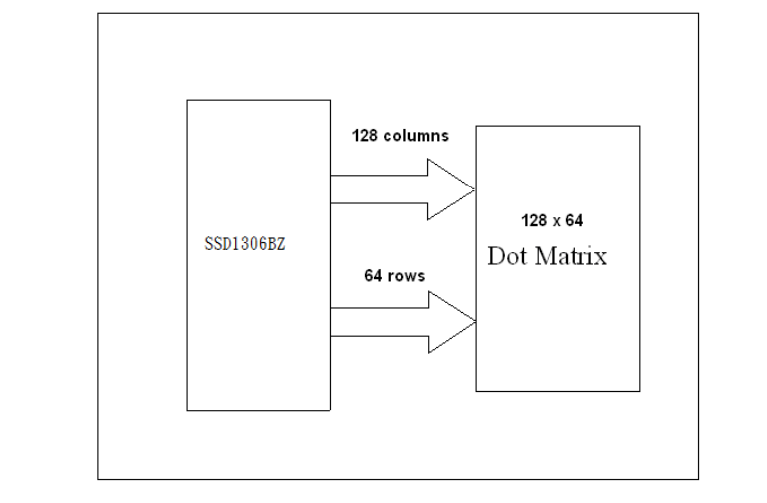
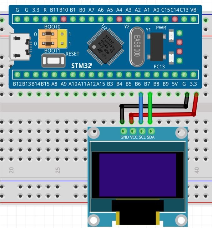
In previous blog we covered a brief overview of how the OLED display works in microscopic level and also understood various types of OLED displays available in the market . In this blog we’ll be discussing how to configure the SSD1306 display with the microcontroller and we’ll be making the embedded driver as well.128×64 display is a dot matrix display , hence 128×64 =8192 total pixels . It is by turning on/off these pixels we display graphical image of any shape . It is the current provided to each pixel that varies the brightness.
HARDWARE DESCRIPTION
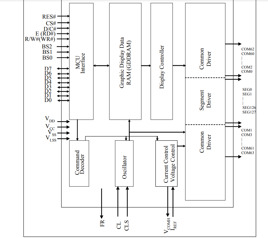
OLED Display chosen is driven by SSD1306 Driver IC although they are other ICs such as SSD1331 which can be used to drive the display . These ICs are CMOS OLED Driver controller for dot-matrix system . OLED has 256 brightness steps .Besides 128×64 , 128×32 display resolution is also available.
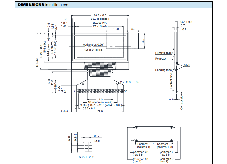
Specification of ssd1306 128×64 OLED
- Display Type: OLED (Organic Light Emitting Diode)
- Display Size: 128x64 pixels
- Display Driver: ssd1306
- Display Colors: Monochrome (White), Yellow, and Blue
- Operating Voltage: 3.3V to 5V
- Interface: I2C
- Operating Current: ~20mA
Display Structure
OLED DISPLAY is mapped using GDDRAM page structure OF SSD1306
GDDRAM or graphic display ram is a bit mapped static RAM . It holds the bit pattern to be displayed. The GDDRAM having size 128×64 is divided into 8 pages from PAGE 0 TO PAGE 7 which is used for monochrome matrix display . When data bit D0 – D7 is sent the row0 gets filled with D0 and D7 is written into the bottom row.
- Display has 64 rows , 128 columns divided into 8 pages .
- Each page has 128 columns and 8 rows.
- Display 128 columns known as segments
- For displaying the graphical data in the first location , page address and column address both are set to 0 with the end address of page and column also being selected
- End of column and End of the page is 7FH and 07H respectively


ADDRESSING MODE
- In page addressing mode, after the display RAM is read/written, the column address pointer is increased automatically by 1.
- If the column address pointer reaches column end address, the column address pointer is reset to column start address but page address pointer not points to next page.
- Hence, we need to set the new page and column addresses in order to access the next page RAM content.
- We need to set lower two bits to ‘1’ and ‘0’ for Page Addressing Mode.
In page addressing mode, the following steps are required to define the starting RAM access pointer location:
- Set the page start address of the target display location by command B0h to B7h.
- Set the lower start column address of pointer by command 00h~0Fh.
- Set the upper start column address of pointer by command 10h~1Fh
In horizontal addressing mode, after the display RAM is read/written, the column address pointer is increased automatically by 1.
- If the column address pointer reaches column end address, the column address pointer is reset to column start address and page address pointer is increased by 1.
- When both column and page address pointers reach the end address, the pointers are reset to column start address and page start address
- We need to set last two digits to ‘0’ and ’0’ for horizontal addressing mode.
- In vertical addressing mode, after the display RAM is read/written, the page address pointer is increased automatically by 1.
- If the page address pointer reaches the page end address, the page address pointer is reset to page start address and column address pointer is increased by 1.
- When both column and page address pointers reach the end address, the pointers are reset to column start address and page start address.
- We need to set last two digits to ‘0’ and ’1’ for vertical addressing mode.
In normal display data RAM read or write and horizontal/vertical addressing mode, the following steps are required to define the RAM access pointer location:
- Set the column start and end address of the target display location by command 21h.
- Set the page start and end address of the target display location by command 22h.
Hardware Pinout
-
SDA
This pin is used to send data between master and slave with the acknowledgement of the master
-
SCL
This is a clock signal that helps keeps the process in synchronization
-
VCC
A power supply of 3.3 V is required . More than 3.3V may damage the module
-
GND
This ground pin is connected to the ground supply

ALGORITHM
- Select the I2C slave address and specify the operation that will be performed i.e Read 0x79 or Write 0x78.
- Set the clock divide ratio and oscillator frequency . Bit 3-0 sets the clock divide ratio , Bit 7-4 sets the oscillator frequency
- Set the multiplex ratio switching to any value ranging from 16-63
- Display start line addressing in which the starting address of the display ram is determined . In our case this is set to zero and RAM row 0 is mapped to col 0
- Set memory addressing mode using page addressing mode, horizontal addressing mode, vertical addressing mode.
Set column address using a triple byte first specifies the column setting , second column start and third column end . Do the same for the page
- Set pre-charge period and VCOMH deselect level
- Entire display is on using A4H and A5H command
- The normal functionality of the display is set rather than inverted
FUNCTIONAL IMPLEMENTATION OF OLED SSD1306 DISPLAY
The I2C devices are recognized by their slave addresses and the format of their address is as follows
SA0 – Provides 2 slave address option to choose from
R/W bit – This bit is to specify the I2C read or write of the operation 1 for read operation 0 for write operation .

For write the I2C address is as follows 0x78
For read the I2C address is as follows 0x79
This function is used to set the X and Y coordinates of display and specifies the point where data is to be displayed .
The function takes in 2 16 bit arguments which are then passed into the variable of the structure SSD1306 , CurrentX and CurrentY
This char type function takes in the pointer of the string , font of the string or char to be displayed and the color of the LCD which is a enumeration having 2 values white and black
This function pushes character by character using the function Putc until the last character is reached and returns the string in the end
Also font in which the text is to be displayed is chosen using the font.c library
This char type function takes in 3 arguments the character of the input string , the font from fonts.c library and the color of the OLED
The function checks if there is space available on the pixel on which the user wants put the data and returns error in case of a collision
Next the size of the font chosen is determined and using the draw pixel function both the X and Y coordinates are updated and in the end the pointer is updated to go through the next character and the previous character is returned.
The Draw pixel function takes in 2, 16 bit X, Y values as arguments .
Next the function checks if the entered values are greater than the width and height of the OLED. The function also checks if the pixels are inverted .
Next the X and Y location are put in the SSD1306_buffer which is a static function
In this function the SSD1306 is initialized using various parameters . The write command for opening the display is sent , next the memory addressing mode is set following which the addressing mode horizontal , vertical , page is set . Next the page start address is set , scan direction of the COM output is set , the start line address is also specified , the remapping of the segment is mapped to 0-127, next the clock divide ratio is set and finally SSD1306 is turned on.
This function is used write data to a single device with the address being defined . The register to which data is to be written is specified and is transmitted using HAL_I2C_Master_Transmit(&hi2c1, address, dt, 2, 10); function
This function is used to write multiple slave devices and the count is updated every time the next device is to be selected.
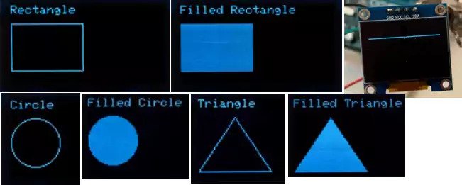
This function is used to draw a line on the display , which initially checks if overflow condition is reached or not, next after displaying the dot on every pixel the X , Y coordinates are updated after checking if the line is a horizontal line or vertical line and the iteration is done until the coordinate X1 , Y1 is reached
This function is used to draw a rectangle on the display using the starting position as mentioned in X , Y coordinates and width w and height h . Using these 4 variables the draw line function is called 4 times .
This function is used to draw triangle using the drawline function and calling it each time for starting and ending coordinates of the line which are (x1, y1), (x2,y2) and (x3, y3) .
This function takes in input x0 , y0 as the starting coordinates of the circle and after calling the draw pixel function and using the radius as the argument the circle is drawn.
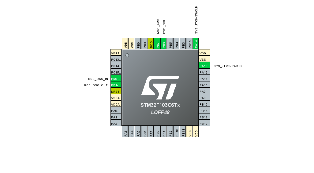
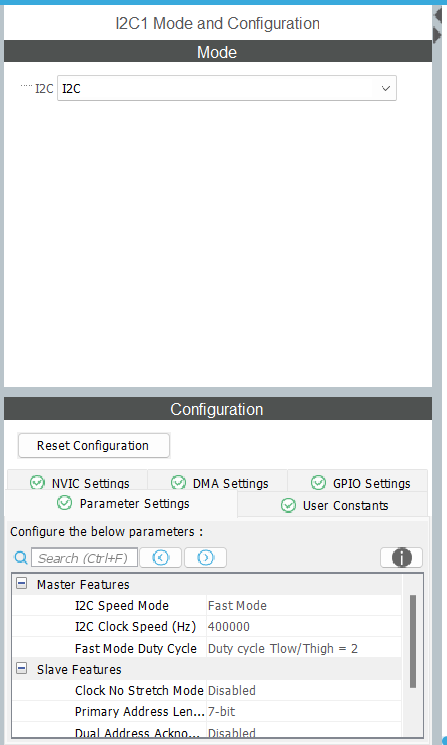
CUBE IDE CONFIGURATION


CODE
To display the score of a game
CODE EXPLANATION
-
STEP 1
This is use to initialize the I2C1 peripheral of the microcontroller
-
STEP 2
This function is used to configure the parameters of the I2C1 peripheral such as clock speed , addressing mode, duty cycle etc.
-
STEP 3
This is used to initialize the SSD1306 chip according to the parameters such addressing mode being page , horizontal , vertical mode , page start address , inverted mode or normal mode, control register and various clock parameters such as clock ratio , oscillator frequency.
-
STEP 4
This function is used to specify the start X,Y pixel of the display
-
STEP 5
In this function the given string is displayed on the OLED display on the font specified along with the color of the background
-
STEP 6
Finally the loop starts and the points to be displayed are updated with every iteration and the GOTOXY function is called each time the no of digits increase i.e 1, 2 etc to keep the number being in the center.