Over 10 years we help companies reach their financial and branding goals. Engitech is a values-driven technology agency dedicated.

Gallery

Contacts

411 University St, Seattle, USA

engitech@oceanthemes.net

+1 -800-456-478-23

Display Screens Sensors and Modules Tech

What is OLED Technology?

OVERVIEW Nowadays we see oled display being used everywhere be it the phones , TVs , laptops or PCs , smartwatches . They sure are better than old chunky CRT TV displays that were bulky and didn’t deliver the desired picture quality , with the introduction of the LCD and backlight LEDs the things sure got better with the chunkiness of the display gone but the picture quality still wasn’t what one desired of but with the release of the OLED display all these problems became a thing of past. OLED or organic light emitting diode were invented in 1987 by Ching Tang and Steven Van Slyke from Kodak but it was until 2004 when SONY released a OLED TV. In fact in CES 2019 , there were some innovative inventions that were released in the OLED domain with the companies trying to come up with foldable display and some exceptional picture quality. TYPES OF OLED Passive Matrix Oled (PMOLED) Pmoleds have strips of cathode , anode and organic layer. The anode strips are perpendicular to cathode strips it is their intersection that makes a pixel . External circuitry applies current to the cathode and anode strips to decide which pixel to light up. They are used in MP3 players , cell phones etc. Active Matrix Oled(AMOLED) Amoleds have full layer of anode and cathode and organic molecules . The anode layer overlaps the TFT matrix array . The TFT array is the matrix circuitry that decides which pixel gets turned on form the image. Since they consume less electricity they are used in TV screens , BillBoards, Computer Monitors. Transparent Oled A Transparent Oled has all the components cathode, anode, substrate transparent and when off the display is 85 percent transparent. When switched ON the display allows the transfer of light in both the directions. Top Emitting Oled The Top Emitting Oled is have substrate that is either opaque or transparent . They are best suited for active matrix design . They are used in smartcards                   Foldable Oled They are substrate that made of flexible metallic foil , plastic . They are durable and are easier to replace in case of damage . They are used in smart clothing , GPS receivers , IC computers. White Oled They are made of white light that is more uniform and energy efficient rather than fluorescent lights. They posses true color of incandescent lights BESIDES THESE OLEDS ARE ALSO CATEGORIZED ON THE BASIS OF BASE COLOUR Monochrome Blue Monochrome white Yellow Colour NO OF PINS 3 Pins (supports only I2C) 7 Pins(supports both I2C and SPI) BASED ON INTERFACE ICs    SSD1306     SSD1331 BASED ON SIZE 0.91 inch(128×32) 0.96 inch(128×64) HOW OLEDs WORKS Both the LCD and OLED have similar display mechanism . The difference lies in the fact that OLED has the smallest display unit made of pixels that are usually 0.3mm x 0.3mm . Inside each pixel they are 3 different type of color filters . When the size of the color filter is reduced then human eye losses its ability to view each color individually and sees them as a mixture. Next each pixel is converted into digital form for future reproduction of the image. Earlier the image reproduction was done using backlight white , colour filters, glass , diffuser . When the light would glow each color filter would light up too. Behind the filters a polarizer lcd sheet is used which reproduces the image , the problem with this was the black colour produced wasn’t exactly black due to the back light being ON constantly . This issue was rectified using tiny light sources for each pixel due to which organic led was used . If we apply positive voltage to the anode termina the electrons would combine with the holes in the LUMO layer producing light. Work is also being done to remove the need for light source and add doping material in the emission layer which will release light of the certain color due to the energy difference in the conduction and valence layer corresponding to their wavelengths FIG -1 SIZE OF A SINGLE PIXEL FIG-2 RGB COLOR FILTERS INSIDE A PIXEL FIG -3 CONVERTING EACH COLOR INTO BINARY FIG -4 CROSS SECTION VIEW OF OLED FIG-5 CHANGING THE ORIENTATION OF THE POLARIZER TO GENERATE DIFFERENT COLORS FIG -6 ELECTRON HOLE PAIR COMBINATION TO GENERATE LIGHT FIG – 7 DOPING OF SUBSTRATE TO GENERATE LIGHT OF VARIOUS WAVELENGTH USE CASES OF OLED DISPLAY Raspberry Pi Based SSD1306 OLED Video PlayerThis project uses Raspberry pi and OpenCv to display videos on the Oled display ESP8266 Weather WidgetThis project used ESP8266 and weather API to display real time weather conditions on the 0.96 inch display. Tinyduino gamepadThe project used joystick , push buttons , arduino uno , custom designed PCB , USB module  and ssd display to play games on the tiny 0.96 inch screen Bluetooth SmartwatchThe project uses 0.96 display , bluetooth module , tiny arduino , lipo battery to connect to the phone and display all kinds of medical stats and time Speedometer for bikes The project uses gps module neo6m and ssd1306 display to show speed of the vehicle on the display and raise an alarm in case of overspeeding.                                                                                                 HOW TO CONNECT THE DISPLAY WITH THE MICROCONTROLLER WE WILL BE COVERING THE DETAILS ON HOW TO CREATE AN EMBEDDED DRIVER FOR THE DISPLAY IN THE NEXT BLOG . IN THIS WE’LL BE COVERING A BRIEF OVERVIEW OF THE 2 METHODS THAT CAN BE USED TO COMMUNICATE WITH THE DISPLAY. I2C SPI I2C Using I2C we’ll be communicating with the microcontroller by the help of SCL the clock

Getting Started and Peripheral Coding STM32 MCU's STM32F1

GPIO Peripheral in STM32F103 MCU

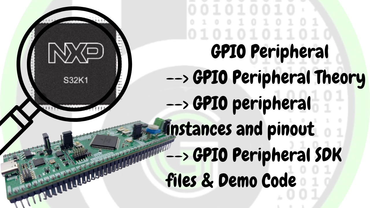
Table of Contents GPIO Theory So now  we’ll talk about GPIO pins . GPIO stands for general purpose input output pins; they are the means for communication between the microcontroller and the external world (using sensors etc).It is signal that arrives on these pins or a signal that is sent or written on these pins that facilitates this communication. These pins can be configured to act as input or output  via the application software(in our case stm32cube ide). The programmer can configure the pins as LOW or 0V or HIGH or 3.3V(or 5V ). These GPIO pins can also be configured to act as  special purpose pins as well where their alternate functionality is exploited . These alternate functionality includes UART , ADC , SPI etc . In the case of UART communication, Transmitter(Tx) and Receiver(Rx) pins are required. GPIO pins can be configured to act as TX or RX pins . Even in ADC the pins are configured to act as Analog pins having 12 bits of resolution . The alternate functions of various pins are shown below: Input floating Input pull-up Input pull-down Analog Output open-drain Output push-pull Alternate function push-pull Alternate function open-drain GPIO Peripheral in STM32F103 All the pins of STM32F103 are grouped in multiple ports as PORT A, PORT B, PORT C As can be seen from Pin configuration chart in the PA1 stands for Port A Pin 1. There are 37 GPIO pins in stm32f103 which are divided as PORT A with 16 pins, PORT B with 16 pins, PORT C with 3 pins and PORT D with 2 pins. Each GPIO  port  has two 32-bit configuration registers (GPIOx_CRL, GPIOx_CRH), two 32-bit data registers (GPIOx_IDR, GPIOx_ODR), a 32-bit set/reset register (GPIOx_BSRR), a 16-bit reset register (GPIOx_BRR) and a 32-bit locking register (GPIOx_LCKR). In the register names, x stands for the port to which pin belongs. If we are configuring pin PA1, it has Port A then registers would be accessed by GPIOA_CRL and etc. Out of above-mentioned registers, GPIO peripheral has 2 most important registers: Direction Register(GPIOx_CRL, GPIOx_CRH)</h3 > Direction register: Set the corresponding pin as input/output pin. Data register(GPIOx_IDR, GPIOx_ODR)</h3 > Data register: where we set the Logic level (High (1)/Low (0)), for the corresponding pin if it is configured as output pin or we read the Logic level (High (1)/Low (0)), for the corresponding pin if it is configured as input pin. Pin Configuration Chart Pin Definitions GPIO Peripheral Block Diagram in STM32F103 First after selecting the pin the port is decided Then after following the arrow the busses are selected based on it: APB/APB1 or AHB After which the clock is enabled to the particular port using either __HAL_RCC_GPIOX_CLK_ENABLE() function or using the RCC AHB1 peripheral clock enable register and selecting the port to which clock has to be provided by enabling it. Methods to configure the GPIO Peripheral Configuring the busses i.e AHB1, AHB2, APB1, APB2 . The AHB bus is faster than APB bus and in case of certain modules they are connected to the same bus .Hence it depends upon the application which bus to use. As can be seen from the picture below the AHB1 takes clock to PORT A , PORT B , PORT C etc . Hence to initialize a pin to a particular port the in RCC AHB1 clock enable register GPIOEN is set to 1 (For Port A GPIOAEN , For Port B GPIOBEN etc) Enabling the clock to that port otherwise the particular pin will not be functional  Creating an instance of the structure and then using the members of the structure set the following:- PIN – Takes the pin no as input GPIO_PIN_X {where X -0 to 15} MODE– Selects the mode the specified pin is supposed to work in . It takes in value Output Push Pull ,Output Open drain PULL- It selects the initial value of the pin and takes value no pull up no pull down, pull up or pull down SPEED- Selects the speed of the working of the specified pin i.e low, medium or high ALTERNATE- Specifies the alternate function performed by the pin UART TX OR RX , ADC etc, GPIO Peripheral SDK using STM32HAL We are going to use STM32 HAL SDK for using the GPIO peripheral of the STM32F103. STM32HAL is a very versatile and robust Software package for using Peripherals of the STM32 Microcontroller family. To know more about STM32HAL, refer to this link. Each STM32 HAL has drivers for all the peripherals of the STM32 Microcontroller(One can navigate to the Driver folder in the STM32F1 HAL local repo installed). These drivers can be configured and enabled to use in the project via the STM32 CubeMX configuration tool, which is also integrated into STM32CubeIDE( just like told in the above section for configuring GPIO peripherals). Will be digging into that part, in the next section. For now, let’s understand the STM32HAL GPIO SDK for STM32F103 MCU. stm32f1xx_hal_gpio.c: This file consists of various macros and  is responsible for the intialization and configuration of the functions which in turn configures the peripheral. stm32f1xx_hal_gpio.h: consists of various structure definitions that help configure various parameters of the pin, enumeration, and various macros stm32f1xx_ll_gpio.c & stm32f1xx_ll_gpio.h: GPIO Low-level driver source/header file, contains functions that configure the GPIO Peripheral registers at the hardware level. These files are the ones that actually interact with the hardware and make it configurable to our needs.  STM32 HAL Functions for GPIO Peripheral Functions are set of instructions that required to perform certain tasks. In general, a function is first declared in header file(.h) and then it is definied in source file(.c) and then called in main.c or application code. It is of the form function return data type, function name and function arguments. In Embedded functions are required to initialize a peripheral or configure it on the basis of various parameters which are passed on using arguments. This information is then passed on to the registers.  List of functions used

AVR MCU Embedded MCU's

Getting started with AVR and Arduino

Home Category Child Category Part I – Untangling the wires: On your journey of exploring the different areas of embedded systems and microcontroller programming, you must’ve come across the term ‘AVR’. This blog (or series of blogs) will try to demystify all the terminologies. Prerequisites Before we proceed, this blog assumes that you already have a basic overview and understanding of what microcontrollers are, what their basic functionalities are, and how they differ from microprocessors. Knowledge of the C/CPP programming language would be beneficial. Table of Contents Introduction Arduino vs AVR The family of AVR microcontrollers Keywords Further reading References Introduction The technical definition of what AVR is, is: The AVR microcontroller is a family of mostly 8-bit microcontrollers developed by Atmel (now Microchip), that follow the Harvard RISC architecture. Let\’s try to break all this technical jargon down. Harvard architecture is a type of architecture where the instructions (program code) and data are stored in different parts of memory. This is in contrast to Von Neumann\’s architecture where no such distinction is made. The following illustration might help you understand the concept a little better. Now coming to the other piece of jargon that might’ve thrown you off RISC. It stands for Reduced Instruction Set-Computer. It is a computer architecture philosophy that generally follows the idea of having smaller and atomic instruction sizes when compared to its counterpart CISC (Complex Instruction Set-Computer), which has relatively bigger instructions. We won\’t be diving into this as this is a topic for another day. Arduino vs AVR Before we move any further let\’s clear one big misconception out of the way. People tend to confuse the terms Arduino and AVR quite often. Although it wouldn\’t be fair to compare these two (it would be like comparing an engine to a car), the following table clearly explains what are the differences between the two. In this article when we use the word “Arduino”, we will be referring to the Arduino platform which includes all the hardware and software made by the company.   Arduino   AVR 1. Is hardware and software platform which includes, but is not limited to: the Arduino IDE, Arduino Uno board, and the Arduino programming language 1. Is a family of microcontrollers developed in 1996 by Atmel. It is only a piece of hardware. 2. The Arduino Uno is a board that is built around the ATMega328, which is an AVR microcontroller. Apart from the microcontroller itself, it has other components such as a USB2.0 cable and a PCB on top of which the components such as resistors and capacitors are wired together. 2. Is a microcontroller that requires additional passive and active components (clock, LEDs, etc.) to be wired up by the end-user for it to work. 3. Products are developed and maintained by Arduino (company) 3. Products are developed and maintained by Microchip Technology Inc 4. An Arduino Uno board:Notice the various components such as voltage regulators, connectors, switches, LEDs that are already soldered onto the board.The rectangular black IC (Integrated Circuit)/chip on the bottom right-hand corner of the board is the engine that drives the car (board), ie, the ATmega328, which is an AVR microcontroller 4. The ATmega328P, an AVR microcontroller: It doesn’t come packaged with any components, which have to be attached by the vendor/programmer themselves Difference Between Arduino and AVR The family of AVR microcontrollers Microchip offers a wide selection of microcontrollers to choose from, each meeting a different set of requirements. They can broadly be divided into three categories. Series Package size FlashSize  Operating Frequency Example ATtiny(TinyAVR) 8-32 pins 0.5kB – 32kB 1.6MHz-32Mhz ATtiny85 ATMega(megaAVR) 28-100 pins 4kB – 256kB 1.6MHz-32Mhz ATMega328 ATxmegaXMEGA 44-100pins 16kB – 256kB 1.6MHz-32Mhz ATXmega128 AVR MCU Family Series Differences The above table isn’t exhaustive as there are many other families of microcontrollers such as the 32-bit AVR32 and the newly released AVR Dx series. The family of microcontrollers you end up choosing, totally depends on the scope of your project. Looking for a very small compact and lower power microcontroller which can automate a basic task, like toggling an LED-based on an input switch? Then go for the ATtiny family. Looking to control a servo motor that is connected to an IR sensor? You definitely won\’t go wrong with the ATmega series. Still, looking for more firepower for controlling multiple sensors? The ATxmega series has got your back. In the upcoming blog, we shall deep dive into one of the most widely loved and used microcontrollers – the humble yet mighty ATmega328. Till next time! Ciao! Further Reading http://ce.sharif.edu/~pourmohammadi/AVR%20Microcontroller%20and%20Embedded%20Systems/AVR%20Microcontroller%20and%20Embedded%20Systems.pdf https://en.wikipedia.org/wiki/AVR_microcontrollers http://www.avrbeginners.net/ References https://www.microchip.com/en-us/product/ATmega328P Intro Video on Device Drivers and Application Code for AVR(Arduino Boards) – YouTube

Stay Updated With Us

Error: Contact form not found.