Embedded Basics Miscellaneous Tech

How to start with Microcontrollers?

Table of Contents

What is Microcontroller?

Microcontroller is a kind of an integrated circuit, which is used in the development of every electronic device around us. From avionics industry for the development of spacecrafts, missiles, rockets, satellites, to the car industry for the development of automotive cars, luxury cars, Electric vehicles, sports bikes not only this but even in medical industry for development of medical equipment’s like ECG’s, vaccine’s, optical equipment’s and even in music and entertainment industry for the development of speakers, mikes, audio amplifiers, stage lights to shooting camera. Also, microcontrollers you find around in our day-to-day life (white goods) in devices like Refrigerators, Ovens, Electric tandoor, grinders, hair dryers, Fans, AC’s etc. Even in consumer electronics televisions, mobile phones, tabs, smart watches, projectors, printers these are also developed with the help of microcontrollers.

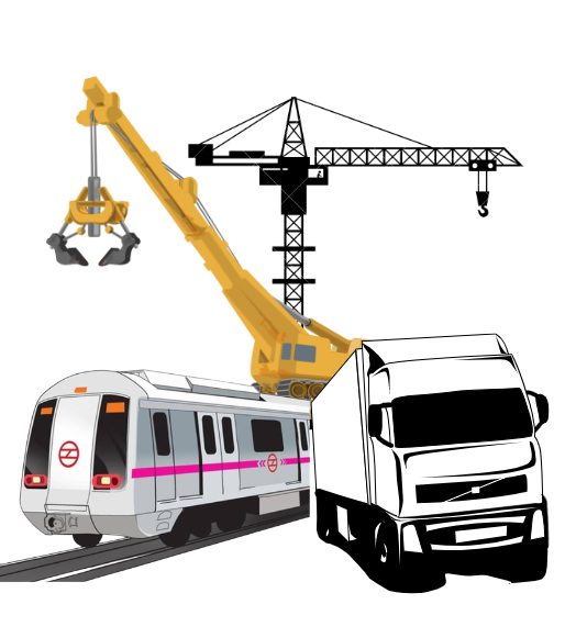
Not only this but even in heavy machines like cranes, JSB, construction vehicles, metros, railways there is need of microcontrollers for their development.

So, you see, if you literally take any electronic/electrical gadget device around you there would be a microcontroller in it in one way or another, from food technology to medical technology to smart homes to smart cities to aircrafts, ships, boats, yachts to electronic meters and list will never end.

Thus, the need of microcontrollers and its knowledge is growing from day by day, as for the development of any embedded device of any kind of industry, there would be a need for microcontrollers.

How do microcontrollers accomplish that?
Microcontroller is an innovative technology that has revolutionize the world and made the electronic items so much feasible for us. Though microcontrollers have been in world since 1960’s. But there are many new inventions and development still going on this field. Well microcontroller is just like a human being.

Just like human beings can do any kind of work same way microcontrollers can be used in any kind of industry to make any kind of gadget.

Analogy of Microcontrollers!

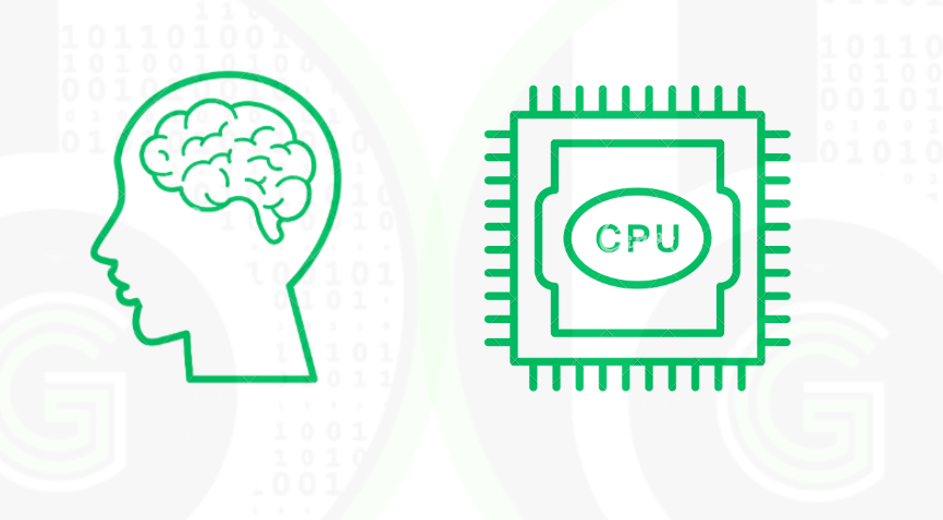
Just like human beings have brain where processing of all data is done microcontrollers have CPU. In the CPU(Central Processing unit), all the processing of data, speed of execution is done. Thus CPU’s are the brain of the microcontrollers.  Often the word CPU is used interchangeably with processor/core.
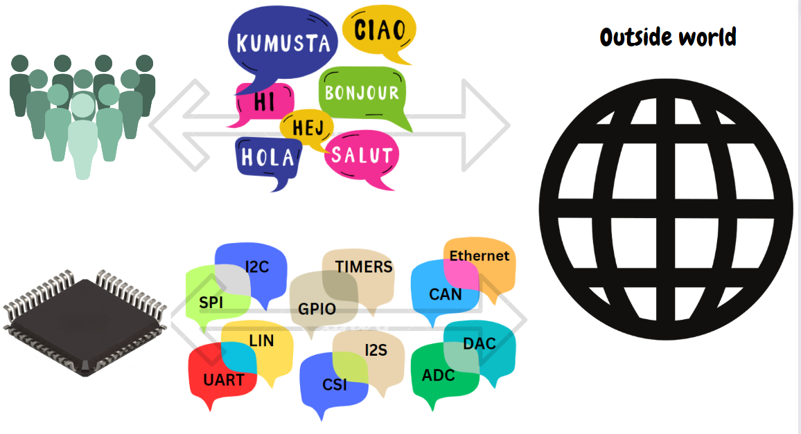
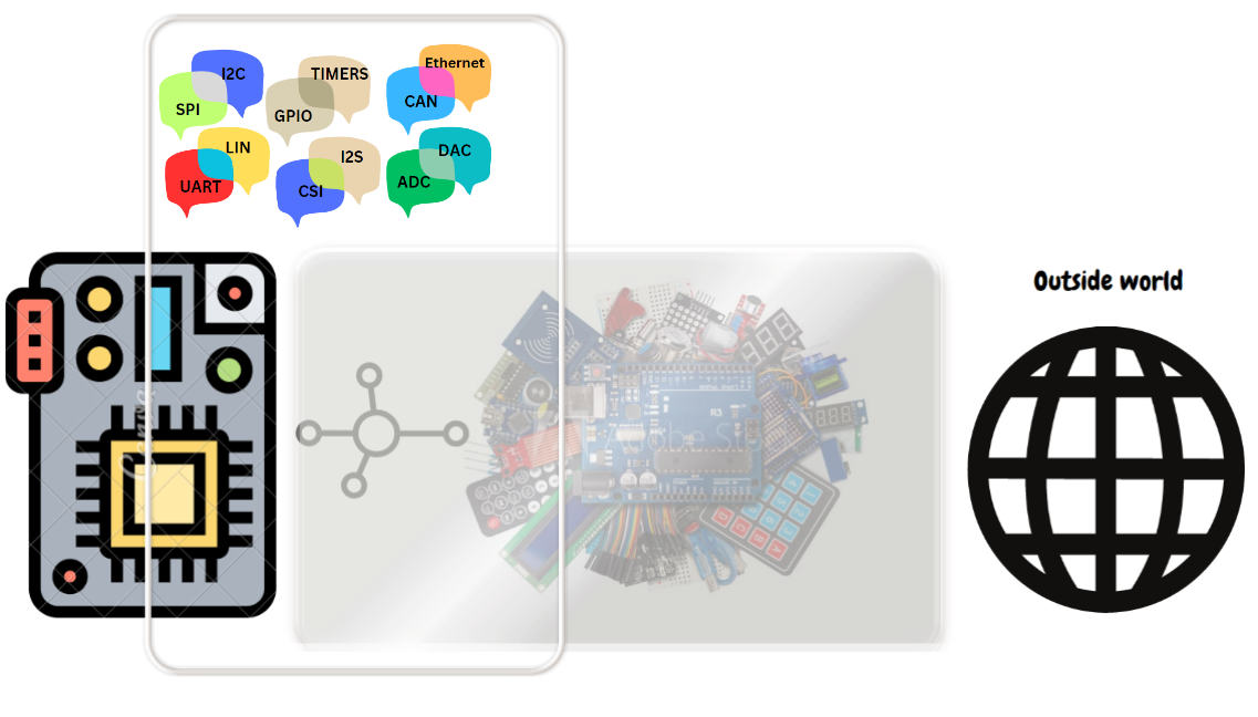
Just like human beings use some form of language to communicate with outside world like English, Spanish, Hindi and etc. Same way microcontrollers use different communication protocols (UART, I2C, SPI, CAN, LIN, cryptography, I2S, CSI  1-wire, and many other) and digital/analog signals(GPIO, PWM, ADC, DAC, TIMERS) to communicate with the outside world. 

Just like human beings have different body parts to interact with outside world, microcontrollers have different peripherals which are used to interact with outside world. For each Communication Protocol and digital/analog signals that are stated above there is some corresponding peripheral in microcontrollers.

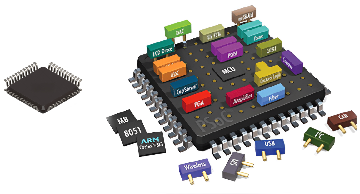
Just like in human being’s brain sends signals to body parts, same way in microcontroller for using peripherals some configurations and programming has to be done to use them, this is called peripheral coding/drivers. That would be explaining in below sections.

Now some sensors and modules are connected to Microcontrollers as an intermediate between the outside world and microcontrollers. And these sensors and modules communicate with specified communication protocols.
  • Just like we human beings have memories of our life, past and things to do, according to which we act and do our daily work. Exactly same way microcontrollers too have memories, difference is just this memory is programmable. According to the program written on these microcontrollers they work. So, it’s like programming the human beings (with Smily emoji). That would be explaining in below sections.

Connecting the analogy of microcontrollers!

Microcontrollers are connected to different sensors and modules according to the industry in which they are being used. Microcontrollers communicate with these sensors and modules by some communication protocol via the peripherals of the MCU. Sensor and modules act as an intermediate between the microcontrollers and world, to get information from the outside world that is input to the microcontrollers(input). Then this data is processed and analyzed by the CPU (brain of MCU), where all these calculations, processing, operations are done. And then information is sent from the microcontrollers(output) to corresponding sensors and modules to show results or control the outside world. And That’s how microcontrollers can be used to make any electronic gadget of any Industry.
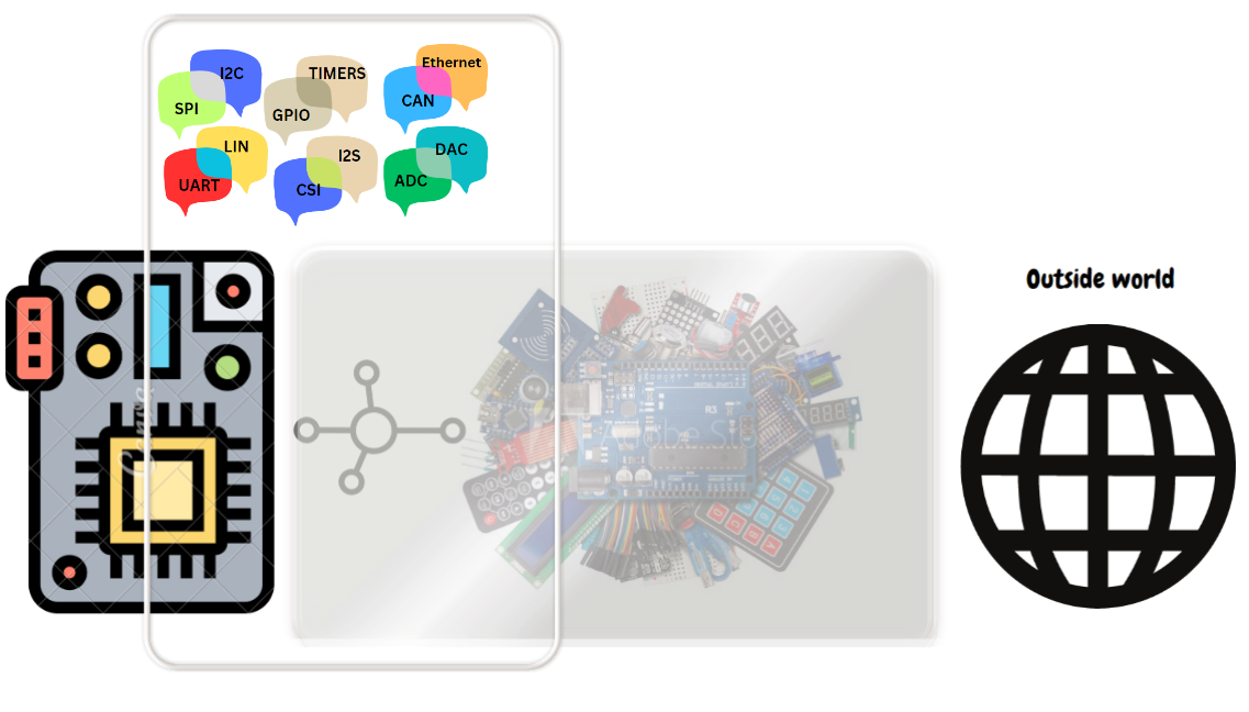
Practical usecases of microcontrollers

Having the understanding of communication protocols and peripherals of the microcontrollers one can make electronic gadgets for number of industries.
Decoding the data from the sensors and modules, and then correspondingly what actions has to be taken, according to inputs. This is controlled by the program Witten on these microcontrollers. That is called as Embedded Software/Firmware development. This program is controls the flow of execution, that what to do, when to do and how to do.
There are many software components in this flow, Device drivers for connecting sensors and modules, bootloader to start the MCU, Peripheral drivers for peripherals of MCU, Hardware Abstraction Layer for code portability, RTOSes for real time computing, Stacks for IoT protocols and etc. For programming the microcontrollers there is need of environment called Software Development Kit (SDK). Microcontroller are programmed using C/CPP language. More on Software development Kit would be told below.
Peripherals are made up off an electronic circuit using resistors, capacitors, op-amps, transistors, digital-analog electronics and miniaturized so small using the VLSI-VHDL technology that these circuits are made to fit inside the tiny chips called microcontrollers
For using the microcontrollers there is need of hardware resources called Hardware Development Kit (HDK). More on Hardware Development kit is told in next blog.
HDK

Microcontroller Vendors/Semiconductor Companies​

Microcontrollers are designed and developed by the Semiconductor Companies. These Companies designs the microcontrollers for different industries (listed above), where these microcontrollers are used for product development.

Semiconductor industry is multi-billion-dollar industry, companies are as big as google, amazon & Microsoft (some are even larger than that). 

Name of Semiconductor companies:

Semiconductor companies not only designs and develop the microcontrollers but instead many other electronic/integrated chips (ASICS, memory chips, sensor chips, IoT chips, discreate electronics, development boards and etc.)Apart from just electronic chips, these companies develop the Software packages, Software Tools, Software Applications (ML, AI based), Hardware tools and also do Core RnD on the next upcoming technologies in the fields like of Automotive, IoT, Avionics, Industrial Automation and list will never end.

Designing of microcontrollers is done via VLSI/VHDL technology and then programming on those microcontrollers to build the applications is done via Embedded Software/Firmware Develpment.

To give a practical use case, you guys must have heard of Arduino. Well Arduino is a development, in which there is microcontroller Atmega 328. This microcontroller is designed and developed by Microchop technologies semiconductor company. Another is NodeMCU, which is also a development board, which has ESP8266 IoT MCU which is designed and developed by Espriff Systems. Most of the hobbyist and students are aware of only these 2 controllers, but there are number of other microcontrollers which are designed and developed. Like STM32 Blue Pill, is a development board which has STM32F103 MCU is ARM Core Based Microcontroller developed and designed by STMicroelectronics. Another is Teensy development boards which has I.MX1062 microcontrollers designed and developed by NXP semiconductors.

At the gettobyte, you are going to find content and tutorial series on different microcontrollers of different vendors. explaining how to use those Industrial microcontroller and tutorials on how to use the peripherals of Industrial microcontrollers to come out of Arduino environment. And get industry ready skills and knowledge in microcontroller field’s

Categories in Microcontrollers​

Categories in MCU’s

Now like there are categorization in human beings in terms of color, features, gender kind of same way there are categorization in microcontroller in terms of:

  • Which CPU architecture and CPU core is used (RISC-V, ARM, CISC, Power architecture, 8-bit architectures), every CPU architecture has some features and specs. Every human has unique brain and only 1 bran, but different microcontrollers can have same CPU core.
  • Bit size of microcontroller (8/16/32 bit Microcontrollers), it’s kind of like amount of data that microcontroller can process. 32 bit can process more data and 8 bit would process less data.
  • Then depending on peripherals support microcontroller has, more peripheral support it has a greater number of applications can be built from it by connecting different sensors/modules to it.
  • Microcontroller’s has memory , as in the end we have to write some program to control the microcontroller, that program is written inside the microcontroller memory. So, amount of memory microcontrollers has (Flash Memory, RAM, SRAM and etc.), depending on that too there is categorizations in microcontroller.
  • Support of Software Development Kit and Hardware Development kit for the corresponding microcontroller.

Chronology to start with microcontrollers
Chronology to start with Microcontrollers

Okay, so lot has been talked about Microcontrollers. Now how to get started with it and in what chronology. Well Microcontroller technology is very vast and has many exciting/interesting topics. Best way to start learning about microcontrollers is by doing Embedded Software/Firmware Development.

From the Embedded Software/Firmware developer, below defined is the best way to start with the microcontrollers:

  • First is take any MCU of any specific vendor (let’s say NXP Semiconductors S32K144 MCU) and then get its development board and debugger/programmer of that MCU. You can get development board and hardware debugger of many different MCU’s from gettobyte website. 

For NXP S32K144 MCU, buy this breadboard compatible eval board, it can be programmed via externa JTAG debugger. Get to know about Pinout and pins description of the MCU.

  • And then setup is its SDK. So understand what Software Development Kit is, why is it needed. Software Development Kit comprises of IDE, code configuration tools, peripheral drivers and software debugging tools.

For NXP S32K144 MCU, Install the S32 Design Studio IDE, Freemaster debugging tool and software package of S32K1 for peripheral drivers(Real Time Drivers). Viewers can refer to S32 DS IDE getting starting blog, for getting to know

  • After that understand the microcontroller architecture, the processor architecture of the MCU. Different kind of interrupts and faults in the MCU. 

Reading the S32K144 Reference manual and Datasheet. First 2-3 chapters of both the docs and try to understand terminologies, keywords which are written, features and specs of S32K144.Then S32K144 MCU has ARM Cortex M4 architecture, so understanding, about ARM architecture and various components in it from its technical reference manual.  Refer to this blog for S32K144 MCU understanding

  • After that, understanding the basic peripherals and communication protocols of the MCU so that one can get to know how application build around MCU.  Theoretical understanding of the communication protocol, digital/analog signals and then relating how is that theory being implemented in MCU by understating the peripheral drivers of that MCU. Every MCU vendor provide the peripheral driver for the corresponding MCU by the name of different names: Real Time drivers, Device drivers and etc.

NXP S32K144 MCU has number of peripheral. NXP does provide peripheral drivers for the peripheral of the S32K144 MCU by the name of Real Time Drivers. I have written well formatted blogs on all the peripherals of s32K144 MCU by explaining the demo example of  peripheral drivers, features of corresponding peripheral in MCU. Refer from here. At gettobyte you can find peripheral driver tutorial on number of Industrial controllers.

  • Now connect different sensors & modules to corresponding peripheral and make the sensor/module run via microcontroller. In this we need to understand at first the working principal of that sensor/module and then understand from its datasheet about how to control that sensor/module via microcontroller so as to run it and then writing its device driver. Device driver is a program written to interface difference sensor/module with microcontroller.

Connect different type of sensor and modules to MCU. At gettobyte their are proper tutorial series on how to connect sensor/module with any MCU. Have connected number of different sensor/module to NXP S32K144 MCU.  Refer to sensor and module section to start.

Different Components in the microcontroller

List of blogs to read to start with the journey

Next Blog To Read

Hardware Development Kit(HDK)
Software Development Kit(SDK)

More Blogs to read to get started with MCU's

SPI Peripheral In STM32F103

Overview So, in this blog we will be covering another alternate functionality of GPIO pins i.e SPI (Serial Peripheral Interface). Previously we hve covered following peripherals implementation in STM32F103 MCU’s. ADC(Analog To Digital Converter) in STM32F103 UART Peripheral in STM32F103 GPIO Peripheral in S32K144 MCU Clock Peripheral in STM32F103 PWM on STM32F103 SPI is a synchronous and full duplex communication between a master and several slave devices. It is used in devices or sensors in which speed is a priority . It operates at data transmission rate 8 Mbits or more. The protocol uses 3 or usually 4 wires for data transmission and receiver .It is used by various sensors and modules such as OLED Display, BMP280 , RC522 , DAC , Shift Registers etc. SPI Theory The SPI uses 2 pins for data transfer SDIN and SDO , SCLK clock for synchronization of data transfer between 2 chips, CE chip select that is used to initiate and terminate the data transfer. SDI  =  MOSI SDO  =  MISO SCLK  =  SCK CE  =  SS MOSI: MASTER OUT SLAVE IN This pin is used to send data from master to slave MISO: MASTER IN SLAVE OUT Lorem ipsum dolor sit amet, consectetur adipisi cing elit, sed do eiusmod tempor incididunt ut abore et dolore magna SCK: SERIAL CLOCK This is used to generate clock to synchronize data transfer between the master and slave device . This is generated by master SS:SLAVE SELECT Used to select the particular slave to send data . Besides SPI communication the SPI interface can switch between I2S communication protocol that is a synchronous serial communication interface. It supports 4 audio standards including the I2S Philips standard, the MSB- and LSB-justified standards, and the PCM standard. The operating modes can be full duplex(4 wires) and half duplex (6 wires) Multi Mode Configuration Multiple subnodes can be used with a single SPI main. The subnodes can be connected in regular mode or daisy-chain mode.   How Data is Transmitted in SPI Initially SCK is enabled that starts the transmission The master sets the SS line low of the slave Data is usually shifted out with most significant bit  first , shifting a new least significant bit into the same register Data in slave side is shifted into least significant bit of the register Hence after all the shifting is done the master and slave has transferred the data If more data is to be exchanged the registers are reloaded and the process is repeated When no more data transmission is there the master stops toggling the SCK and deselects the slave using SS   SPI Peripheral Bus Modes Before discussing about the various bus modes we will be discussing the clock phase and polarity i.e CPOL:Clock Polarity and CPHA:Clock Phase and it is the combination of CPOL and CPHA that is referred to as Bus Modes. CPOL = 0  Active state of clock = 1 Idle state of clock= 0 Means the sampling on the first edge      CPHA = 0 – Data is captured on the rising edge and output on falling edge      CPHA = 1 – Data is captured on the falling edge and output on the rising edge        CPOL = 1 Active state of clock = 0 Idle state of clock = 1 Means sampling is on the second edge          CPHA = 0 – Data is captured on the falling edge and output on rising edge        CPHA = 1 – Data is captured on the rising edge and output on the falling edge SPI Features in STM32F103 Full-duplex synchronous transfers on three lines   Simplex synchronous transfers on two lines with or without a bidirectional data line 8- or 16-bit transfer frame format selection  Multimaster mode capability   8 master mode baud rate prescalers (fPCLK/2 max.)  Slave mode frequency (fPCLK/2 max)   Faster communication for both master and slave   NSS management by hardware or software for both master and slave: dynamic change of master/slave operations   Programmable clock polarity and phase Programmable data order with MSB-first or LSB-first shifting  Dedicated transmission and reception flags with interrupt capability   SPI bus busy status flag   Hardware CRC feature for reliable communication:   – CRC value can be transmitted as last byte in Tx mode  – Automatic CRC error checking for last received byte  Master mode fault, overrun and CRC error flags with interrupt capability   1-byte transmission and reception buffer with DMA capability: Tx and Rx requests SPI Instances in STM32F103 SPI instances vary from microcontroller to microcontroller from 1 in stmf103c6t6a to 6 in stm32f7 each having different pins NSS pulse mode , TI mode and hardware crc calculations SPI1 features PA5 as SCK , PA6 as MOSI  and PA7 as MISO SPI2 features PB3 as SCK, PB4 as MISO and PB5 as MOSI.  NSS Management in SPI protocol for STM32F103 NSS line can to be driven via 2 modes Software Mode- SS is driven internally by firmware Hardware Mode – A dedicated GPIO pin is used to drive the SS line Also NSS features NSS output and output disabled mode. Output mode is used only when device operates in master mode and it is disabled allowing mutli master capability NSS hardware mode must be used in TI mode . CPHA and CPOL are forced to conform to Texas Instrument (TI) protocol requirements. In this NSS signal pulses at the end of every transmitted byte APPLICATIONS OF SPI PROTOCOL Application 1 Memory Devices- SD-Card, MMC, EEPROM and FLASH Application 2 Sensors- Temperature and pressure (BMP280) Application 3 Control Devices -ADC, DAC, Audio Codec Application 4 Others- Camera Lens , RTC, LCD , Touch Screen RFID Module interfacing with STM32F103 W25Q SPI Flash Memory ST77389 LCD Display with STM32F103 NRF24L01 RF Module with STM32F103 How to Configure SPI Peripheral for STM32F103 We would be using STM32 HAL and STM32CubeIDE for using the SPI peripheral in STM32F103 in this blog tutorial series. SPI BLOCK DIAGRAM SPI CONFIGURATION ALERNATE FUNCTION MAPPING CONFIGURATION IN STM32CUBEIDE FIG 1- Selecting MOSI, MISO , SS and SCK pins

Read More »
Automotive Protocols
Rohan Singhal

Introduction to CAN Communication

Table of Contents   Why Was the CAN Protocol Introduced? Let’s start from the basics: why did we need the CAN protocol in the first place? Imagine the electronics in a car before CAN was introduced. Each part of the car’s electronics had to be directly wired to every other part it needed to communicate with. This point-to-point wiring system had some big problems: Too Many Wires: As cars got more advanced, they needed more electronic control units (ECUs) to handle all the new features. Each new feature meant adding more wires, making the system very complicated and heavy. High Costs: More wires didn’t just mean more complexity; it also meant higher costs. Building and maintaining such a complicated wiring system was expensive, and finding and fixing problems in all those wires took a lot of time and money. Hard to Expand: Want to add a new feature to the car? That meant even more wires and changes to the existing setup, which was a real headache. The system wasn’t built to easily handle new additions. Interference Problems: With so many wires, there was a lot of electromagnetic interference (EMI). This interference could mess up the signals being sent through the wires, making the whole system less reliable. Explaining the CAN Protocol The Controller Area Network (CAN) is a robust protocol for connecting electronic control units (ECUs) in vehicles and other distributed systems. CAN was introduced to address the need for a more efficient, reliable, and flexible communication system in automotive applications. Let us explore how CAN works, starting with its fundamental layers. The Physical Layer of CAN The physical layer of CAN consists of a two-wire bus system called CAN_H (high) and CAN_L (low). Data is transmitted differentially, meaning the voltage difference between the two wires represents the actual data. This approach provides excellent resistance to noise and interference, ensuring reliable communication among all nodes on the network. Data Link Layer in CAN The data link layer is responsible for managing the data exchange between nodes on the CAN network. It consists of several key functions: Framing: CAN frames consist of several fields, including the identifier, control, data, CRC, ACK, and end of frame. These fields structure the data and control information for transmission. Addressing: Instead of traditional addresses, CAN uses message identifiers for addressing. Each message has a unique identifier that determines its priority and relevance to nodes on the network. Error Detection: CAN employs multiple error detection mechanisms, such as the Cyclic Redundancy Check (CRC), acknowledgment checks, and form checks. If an error is detected, the erroneous message is discarded, and an error frame is transmitted. Arbitration: When multiple nodes attempt to send messages simultaneously, CAN uses a non-destructive bitwise arbitration process. The message with the highest priority (lowest identifier value) wins the arbitration and continues transmission, while others wait for the next opportunity. Importance of Synchronization Synchronization is critical for the correct operation of the CAN network. To achieve this, all nodes synchronize their clocks at the start of each message transmission and continuously resynchronize throughout the message. This synchronization ensures that all nodes interpret the bit timings accurately and maintain a consistent understanding of the message. Hard synchronization occurs at the beginning of every message. When a node receives the start bit, which is indicated by a transition from recessive to dominant, it aligns its clock with that transition. Resynchronization happens throughout the entire message. As the message is being sent, nodes continually adjust their clocks based on the expected bit timings. If a node detects that a bit transition occurred earlier or later than expected, it adjusts its internal clock to stay in sync with the others. Exploring the Versions of CAN Protocol The Controller Area Network (CAN) protocol has evolved over time, leading to various versions, each offering enhancements over its predecessors. Here, we’ll overview the different CAN versions, with a primary focus on CAN 2.0. Versions of the CAN Protocol 1. CAN 2.0A (Standard CAN) Identifier Length: 11 bits Message Size: Up to 2,048 unique message IDs Data Speed: Typically up to 1 Mbps Features: Standard data frames and error detection mechanism. 2. CAN 2.0B (Extended CAN) Identifier Length: 29 bits Message Size: Up to 536 million unique message IDs Data Speed: Typically up to 1 Mbps Features: Extended identifier field for more complex applications. 3. CAN FD (Flexible Data Rate) Enhanced Data Rate: Supports faster data transmission rates, up to 8 Mbps Data Length: Up to 64 bytes of data per frame Features: Flexible data rate and extended data field for more efficient communication. 4. CAN XL Higher Bandwidth: Supports even faster data rates, exceeding 10 Mbps. Extended Data Length: Capable of handling larger amounts of data Features: Improved protocol efficiency and higher performance for demanding applications Focus on CAN 2.0 While all versions of CAN offer unique advantages, our primary focus will be on CAN 2.0, the foundation of the CAN protocol. CAN 2.0A (Standard CAN) CAN 2.0A FRAME STRUCTURE OVERVIEW 1. Arbitration Field The Arbitration Field is crucial for determining the priority of the message during arbitration: SOF(Start of Frame); 1 bit Determines the starting Identifier: 11 bits Uniquely identifies the message. Lower values have higher priority. RTR (Remote Transmission Request): 1 bit Indicates if the frame is a data frame (0) or a remote frame (1) requesting data. 2. Control Field Reserved bit: 2 bits DLC (Data Length Code): 4 bits Specifies the number of data bytes (0 to 8) in the Data Field. This allows the receiver to know how many bytes to expect. 3. Data Field Data Field: 0 to 8 bytes Contains the message content. 4. CRC Field CRC (Cyclic Redundancy Check): 15 bits For error checking of the Data Field. CRC Delimiter: 1 bit (recessive). 5. Acknowledgment Field ACK Slot: 1 bit (dominant if the frame is received correctly). ACK Delimiter: 1 bit (recessive). 6. End of Frame End of Frame: 7 bits (recessive). 7. Interframe Space Interframe Space: Variable recessive bits. Interframe Space and

Read More »
Peripheral Drivers(Non Autosar)
Kunal Gupta

FlexCAN Peripheral Software Stack Explanation using NXP S32K144 MCU

Overview and motive Objective is to: To get to know what is FlexCAN driver and its features. To Understand How to use FlexCAN Driver(software environment setup and chronology in software configuration)). FlexCAN Driver GUI explanation for configuring FlexCAN Peripheral. Relation of functions of FlexCAN Driver functions via FlexCAN peripheral features. In Depth Understanding of FlexCAN driver functions/data types, with questions like What and why? Chronology of APIs for using basic features of FlexCAN Peripheral for doing CAN communication(How and When?) By basic features we mean the CAN transmission and reception via Mailbox and FiFo mechanism using polling&Interrupt method. What is FlexCAN Driver FlexCAN Driver are set of libraries which are used for using FlexCAN peripheral to do CAN communication via NXP S32K1xx Microcontrollers. Here by library, we mean a set of .h and .c files written in c language. These set of FlexCAN libraries are: Library of FlexCAN Peripheral Hardware registers. Library for FlexCAN Peripheral Interrupt Handlers. Library for FlexCAN peripheral API’s. Miscellaneous files for FlexCAN. Now in FlexCAN Driver there are 3 sets: FlexCAN_Ip.h/.c FlexCAN_Ip_Hw_Access.h/.c FlexCAN IP_Irq.h/.c 3 extra header files: FlexCAN_Ip_DeviceReg.h/FlexCAN_Ip_Types.h/FlexCAN_Ip_Wrapper.h: The first one contains the function and data types through which different features of FlexCAN peripheral are used. Features like of sending data, receiving data, configuring message id filter table and etc. It contains functions like: FlexCAN_IP_Send(). FlexCAN_IP_receive, FlexCAN_IP_RXFIFO and etc. The Second one also contains the functions and data types through which FlexCAN Peripheral registers. Are accessed. Kind of like Bare Metal codes of FlexCAN peripheral are written in this files. And the Functions of this file are used by FlexCAN_Ip.h/.c files. Third one contains the function definition and data types for for IRQ handler of FlexCAN Peripheral And the last one contains the misceeleneours Data types and macros for using flexCAN peripheral. In our application code, we are just going to add FlexCAN_Ip.h header file to access the FlexCAN Driver in our code. And these files are located in the root directory of S32 DS where software installtion of RTD package takes place. FlexCAN Driver and Code Configuration tool relation. Now for using the FlexCAN peripheral, there is a feature of code configuration tool in S32DS via which we can configure the FlexCAN Driver in Gui base. That is instead of writing code, we can confiure how to use FlexCAN Module by GUI presentation. The code configuration tool in S32 Design Studio, generates the set of .c/.h files for FlexCAN peripheral. These are different from library files which I have explained above.  In these generated files it defines and initializes some of the variables. These variables are then used by FlexCAN APIs in the application code. This support of code configuration tool makes it easy for configuring FlexCAN module in easy way via GUI presentation and variables which are generated by code configuration tool are used as parameters in FlexCAN APIs to use them in application code. So, in short to say, code configuration tool generates the values of some of the parameters that has to be send in FlexCAN Driver API. Closure of FlexCAN Driver: There are number of files, functions and data types but for now we are going to concentrate on those which will be required for using FlexCAN in Standard CAN, in normal mode for transmitting and receiving via mailbox and FiFo mechanism. In FlexCAN library there are number of functions and data types through which all the features of FlexCAN peripheral can be used. But we are not going to dwell into all functions and data types. We are just going to cover the functions and data types through which we can send and transmit can data via mailbox/rxfifo mechanisms. As this is the scope of this course and module, for other functions and features you can explore our Advance CAN Courses or can reach out to us privately, Software to install to use FlexCAN Peripheral Driver To use FlexCAN Peripheral Driver, we need to install following things in your Host Desktop/PC: S32 Design Studio IDE 3.4 or 3.5 (any will work though here, we are going to use S32 Design Studio 3.4) S32K1 Real Time Drivers Version 1.0.0 S32 Design Studio 3.4 S32K1 Real Time Drivers Version 1.0.0 S32K1 RTD V1.0.0 is Software Stack for using NXP S32K1xx microcontrollers. It Contains Peripheral Driver library files for using the S32K1xx microcontroller peripherals. It supports all peripherals of S32K1xx MCU’s.  This Software Stack contains 2 packages: Autosaur MCAL layer complaint and standard based peripheral driver files for S32K1xx MCU’s. It is Autosar 4.4.0 complaint. Non-Autosar based peripheral driver files for S32K1xx MCU’s.  It is a collection of peripheral drivers designed to simplify and accelerate application development on NXP microcontrollers. From Learning point of view and long-term skill development, having handson with Autosaur MCAL layer based peripheral driver file would be a good starting point. But as a fresher it might be more challenging to start with autosar standard. So In this blog, we are going to explore Non-Autosar based peripheral driver for FlexCAN module.  Further once having basic Handson with Non-Autosar, will explore Autosar MCAL layer based peripheral driver. Refer to this blog/video to get to know how to install S32 Design Studio 3.4 and Install S32K1 Real Time Drivers v1.0.0. Also it is recommended to explore Code Configuration Tool and Project Creation Modules of S32 Design Studio IDE, so as to get understanding how to use S32 Design Studio throughout the learning cycle. How to use FlexCAN Peripheral Driver FlexCAN Driver can be used via S32 Design Studio Code Configuration tool which provides Graphical User Interface manner in S32 Design Studio IDE, through which we can generate the FlexCAN driver libraries and code automatically in our project. This thing makes it easy to develop applications fast and easy way. The Code Configuration tool generates 2 things: Library Files to use FlexCAN Peripheral. Configured parameters in the form of Data Types (structures, macros, arrays and etc.), which are used as input parameters in different functions of library files. Chronology to follow

Read More »

Starting with RTOS: FreeRTOS

Table of Contents Intro From this blog, we will be starting with RTOS(FREERTOS). In RTOS there are many concepts & things related to kernel, tasks management, task scheduling, IPC, and many other terminologies. In the tutorial series, we are not going into a theoretical understanding of the RTOS topics, we would be mainly focusing on developing different applications in RTOS. Like how to use mutexes, and semaphores in different applications, we will get into the RTOS kernel and understand its different components like scheduler, task management and etc., compare different scheduling algorithms in terms of time and how to create multiple tasks and pass information between them, how to use Software timers, queues and etc. while writing firmware for industrial projects. As there are many resources & tutorials to understand these theoretical concepts and how to use RTOSes APIs to build different kinds of applications is not much there. So, we would be focusing on that thing. RTOS is used in applications like that AGV(Automated Guidance Vehicles), Automotive ECU, and industrial automation products (Like metering instruments, industrial smart sensors and etc.). I have a personal interest and passion for these, so I would be making projects using RTOS related to these by interfacing sensors and modules used in these applications. Ultimately making the different tasks run together to utilize the power of RTOS to make an efficient project. To Know about what RTOS is, refer to this blog What is Real Time Operating System (RTOS) | gettobyte Now to start with RTOS, there are many open source RTOSes available like FreeRTOS, embed OS, Zypher OS, ThreadX OS and etc. But starting with FreeRTOS would be my choice that too with STM32 because the integration of STM32CubeIDE with FREERTOS is pretty easy & gives an easy starting point for beginners. Subsequently, we will migrate to NXP controllers with FreeRTOS. Once getting hands-on with FreeRTOS via STM32. Requites: Bare metal coding On MCU’s (Register level programming, working of MCU’s, SoC/processor architecture, boot process: linker script, startup code, GNU GCC, Debugging and etc.). Knowledge of peripheral of UART, I2C, SPI, ADC, Interrupts, DMA and etcC/CPP programming, etc). Device driver development to integrate different sensors & Modules with MCU. (Datasheet reading, communication protocols, sensors and modules working/Cpp programming). Knowledge of C/CPP programming. Software Development Kit, IDE, HAL, RTD drivers and etc. FreeRTOS What is FreeRTOS? FreeRTOS is Real Time Operating System, which is highly used in industry. It is also best recommended for beginners to start with if one wants to learn RTOS, because of its wide number of resources available, documentation, and community support. FreeRTOS is a market-leading embedded System RTOS, which is available for many processor architectures, it supports more than 40 processor architectures including ARM cortex processors. Also portable to a wide number of compilers and hardware platforms. FreeRTOS is supported by a wide number of silicon vendor chips like NXP Semiconductors, STMicroelectronics, Texas Instruments, and many others. You can find a full list of that here: Microcontrollers and compiler toolchains supported by FreeRTOS. Features of RTOS Highly configurable kernel. FreeRTOS has Microkernel architecture. Pre-emptive or co-operative operation. Inter Processor Communication techniques like Mutex and Semaphore for synchronization. Support for message queues. Software Timers. Event groups. Memory management to maintain heap memory. Also, advanced features for debugging the tasks in Real Time. FreeRTOS Kernel The kernel is the most important thing and core of the RTOS. For the understanding you can have analogy that Human body is RTOS, and Human Brain is RTOS kernel. As without our brain we can’t do any work and loose our capabilities. Same without the kernel, RTOS can’t work. It is kernel which makes electronic devices, a multitasking system. It is kernelling whose responsibility is to run different tasks and have communication between them. Kernel act as the interface between system resources and user application. Kernel has different services for making multitasking system. Just like human brain has different biological parts to make us work. ( In the upcoming blogs and in this also, i would be using analogy of Human brain and Human body for understanding). The basic services of RTOS kernel are:  Task/Process Managment (Creation and deletion of tasks) Task/Process Scheduling (Scheduler) task/Process synchronization (Inter Process Communication) Memory Managment (heap & static) Interrupt Handling Error/Exception handling Coming to the FreeRTOS, it has highly configurable kernel. We can configure how to use the FreeRTOs kernel and which features/services of it. FreeRTOS is configured by FreeRTOSConfig.h header file. This file contains application specific definitions to configure FreeRTOS kernel. Every RTOS has one such configuration file which has macros, which can be enabled or disabled. Like we can configure which scheduling algorithm to use, how to create the tasks (static or dynamic), which IPCs to use for communication between tasks, enabling of run-time trace and debug features. When you will download the FreeRTOS kernel zip file, you will find many numbers of files. But core FreeRTOS is runned by just 2 files tasks.c and list.c. They are located in FreeRTOS/Source directory. In addition to these files, imp files whose Api’s we would be using are queue.c, timers.c, event_groups.c, croutines.c. Examples of RTOS Kernel: Mach QNX VXworks FreeRTOS Chibios ThreadX mbedOS FreeRTOS Libraries In addition to FreeRTOS kernel, there are add on libraries to extend the RTOS functionality. FreeRTOS+: To add support of TCP/IP stack and command line interpreter. FreeRTOS Core: To add support of cloud connectivity with HTTP, MQTT, JSON, Cellular interface. FreeRTOS AWS: To add support of AWS services. How To Start with RTOS? So, as of now, I have told you many things about RTOS and FreeRTOS. Most of you must have come up with that now how to start with FreeRTOS to learn RTOS. When we go to the FreeRTOS website for starting with RTOS, there are many things on the website, lots of documentation, articles, and resources on the website that might become overwhelming and confusing for beginners to start with it. At least for me, it does become like that, so I

Read More »
Getting Started
Kunal Gupta

Getting Started with S32 Design Studio Part 3

Objective of This blog Understanding the code: Talk about different views. IDE Properties and Configurations Building & debugging the code: Debug configurations and how to use Understanding the Code Now after code configuration, our code will be generated. We can see the project files/folder in Project Explorer and write/modify/develop the c/cpp code on the code editor. As shown below. Now it’s time to explore the features S32 Design Studio provides for code navigation and development. Now in this section, I am going to talk about different features/views present in S32 Design Studio for Embedded Code navigation/development. Text Editor View Outline View Console Project Explorer Search Text Editor View Text Editor view: This is the main view, onto which programming is done. Double clicking on any file from Project Explorer will open the open in text editor. We can configure the Text Editor by going to Window->Preferences. We can configure Text editor features like Line number, White space characters, Text Editor Colors. It’s good to explore such features to make the development process on S32 DS interesting. Outline View Outline view: This is one of the best and most useful view.  The Outline view displays an outline of a structured C/C++ file that is currently open in the editor area, by listing the structural elements. As you can see, this view makes very easy for navigation in the corresponding .c/.h file. Console Console: Console is the place where we can see the Verbos of the compilation process of our project. During compilation process. all the errors and warnings are listed in console window.  Console view Project Explorer Project Explorer: Project Explorer view is the one where we can see our project, when it is created or opened. One can see the proper folder structure and files which are their in our project. Project Explorer view in S32 DS By left clicking, on the project in Project Explorer, we can configure our project. Project Explorer in S32 DS We can configure the project in terms of New File/Folder Creations in our project, Build Configurations and SDK management of our project.  One of the most important options in this list is Properties, where we can configure Project setting of our project. I leave this section to explore on own, if you face any issue or want to know things mention them in below comment section. Search Search: Often during the course of Embedded Software development, we would be dealing with the large Project’s in which there are 1000’s of lines of code written in single file and 100’s of files are there. So, in that case using the search view makes things easy to locate. IDE Properties and Configurations Window-> Editor Window ->Preferences Help -> S32 DS Extensiona nd Updates Help -> S32 Check for Updates Help -> Install New Software Help -> Help Contents How to Build the Code in S32 Design Studio IDE Step 1 Step 2 Step 1: First go to file and click on the new tab and then click on the type of project you want to build in the IDE ex :- example project, library project, application project, makefile project, c/c++ project etc. Let’s start with the example code. So, firstly go to the menu bar and click on file and then tab the new button on the file and select the first option that is projected, for  example this will show in the below fig. After this a popup will come and choose the controller in our case it is s32k144 then search the controller and choose the project from the predefined code in this case we are opne the hello world example code. This will be shown in the figure below. Choose the project name and then click on the finish tab. After this a popup will come and choose the controller in our case it is s32k144 then search the controller and choose the project from the predefined code in this case we are opne the hello world example code. This will be shown in the figure below. Choose the project name and then click on the finish tab. Now you can clearly see the project in the project explorer window . Step 2:  For building the project you can simply right click on the project name and click on the build project and then your project is start building you can see this in the below fig If the build is successfully done then the output is shown in the fig below. Debugging tools supported in S32 Studio Different types of hardware debuggers in s32 design studio. there are two types of hardware debugger in S32 design studio which is supported by the S32 design studio SEGGER J-LINK debugger SWD based PEMicro debugger SEGGER J-LINK debugger The J-Link Debugger is a popular hardware debugger and programmer developed by SEGGER Microcontroller, a company specializing in embedded systems and software tools. J-Link is widely used in the embedded development industry and provides a range of debugging and programming capabilities for various microcontroller architectures and development environments. GDB PEMicro GDB PEmicro is a debugger interface that allows the GNU Debugger (GDB) to communicate with P&E Microcomputer Systems’ hardware debuggers and programmers. It enables developers to use the GDB debugger, a powerful and widely used open-source debugging tool, in conjunction with P&E Micro hardware to debug and program microcontrollers and embedded systems. Here’s how GDB PEmicro works and its key components: GNU Debugger (GDB): GDB is a widely used and versatile debugger for various programming languages and platforms. It provides features such as setting breakpoints, examining and modifying memory and registers, stepping through code, and more. GDB is commonly used in embedded systems development. P&E Micro Hardware Debuggers: P&E Microcomputer Systems produces a range of hardware debuggers and programmers designed for embedded systems development. These debuggers, such as the Multilink and Multilink FX, are used to connect a host computer to a target microcontroller for debugging and programming purposes. GDB PEmicro Interface: GDB PEmicro is essentially

Read More »

Getting Started with Firmware Development

See around yourself, we all are surrounded by electronic gadgets around ourselves. The mouse which you are using to navigate through desktop, the Earphones via we all used to listen to music and show off our styles while traveling!!!, the doorbell we ring in homes and see who is outside through video, wireless car keys through which we open our cars, high volume speakers and decks we enjoy dancing on playing the music of our choice when we go to pubs/discos or parties, automation in cars which we see in the forms of lights, automatic systems, high graphics infotainment along with cameras and wireless systems, setup boxes, medical devices like oximeter, sugar, and blood pressure machines. The list will not stop but the size of this blog will get par. All the above examples which I have listed can be termed as Embedded products. Embedded Products are like a silent servants of the modern technological society, as most of the time people are not aware of it but they keep on doing their work Silently and efficiently. One thing in common in all types of Embedded products is the presence of Microcontrollers or Microprocessors. Microcontrollers or Microprocessors are like the brain of embedded products.  Microcontrollers or Microprocessors are digital systems as they only understand binary language that is 0 or 1’s. Now the thing that makes these microcontrollers and microprocessors different from the human brain is that we can program these digital systems. Here comes the Embedded Software/Firmware Development. What is Embedded Software/Firmware Development? Basically, the programming that is done into microcontrollers/microprocessors is termed Embedded Software Development. The term Embedded makes this different from traditional Software Development ( Web/App Development).By the term embedded, it means that their is s Embedded products have a constraint of memory, so programming language has to be there that is of less size and easily be converted to binary language of 0 & 1’s. Programming languages that are widely used: are C and CPP language. Microcontrollers/Microprocessors are physical hardware that can be felt, thus Embedded Software Developers do need some hardware knowledge( like that of Electronics and Computers).  Now the difference in Embedded Software and Embedded Firmware is not much. Both of these are used interchangeably in embedded domain. Embedded Firmware is used when we are developing programs very close to hardware like: Device driver development, Peripheral Interfacing, Sensors and Modules integration. Embedded Software is much more inclined towards Hardware Abstraction Layers(HAL), RTOSes, Wireless protocol stacks, Code portability on different platforms. Need of Embedded Firmware/Software Development. Embedded Software/Firmware development is niche R&D skill in modern world technology whose scope and demand will only increase with growing technologies. All modern world technologies which we see around ourselves:  AR-VR gadgets, Industrial PLC-HMI’s, Next Generation Automotive cars, Internet of Things, Aircrafts, Avionics and many more can only be build by the help of Embedded Software/Firmware Developers. Because it is role of Embedded Software Developers to interact different hardware subsystems interact with each other( through programming and coding) and made the Embedded product work. How to get Started with Embedded Firmware Development. I hope by now you have get bit of clarity and idea about Embedded Firmware Development and its need. Also the kind of industries one can work on after getting this skill. These are very important things to know before actually start learning any skill. As learning a skill is long process and one need good and strong motivation down the line to stay dedicated to learn that skill. Essential things to learn for Embedded Firmware Development. As if now I have talked much about the high end technologies and big flashy words. But now lets get down to basics and actually see how to learn this skill. Essential things to learn for Embedded Software/Firmware Development. C/CPP language–> This is de-facto and most important. As 95 percent of time programming language which is used by embedded developers would be C/CPP language. Both of the languages are more and less same apart from some concepts. Concept of pointers, bit shifting/bit manipulation, functions, types of data types, strings and arrays are the some concepts that should be gone through. Below are some of the books which one can refer for learning basics of C/CPP. Understanding and Using C Pointers: Core Techniques for Memory Management Object-Oriented Programming in Microsoft C++ Pointers on C by Kenneth Reek  Computer Architecture and Organization –> Okay so done with programming part, now hardware knowledge plays equally important role. As Embedded Software/Firmware developers will be programming on Microcontrollers (MCU)/Microprocessors (MPU), so knowledge of them is essential. What exactly is Microcontroller? How do they work? Different kind of architectures in MCU/MPU, difference between MPU&MCU, Boot Process in MPU/MCU, getting familiar with terminologies related to MPU/MCU world are some of the thoughts you can start learning about these. Below are some of the books which one can refer for learning about Computer Architecture and Organization. Computer Organization and Architecture: Designing for Performance Computer system architecture by morris mano One of the best ways to learn these languages is by reading already built in codes. 3. Basic Electronics and Electrical knowledge: Okay so this is the part because of which majority of people after starting initially with Embedded Development left it further in college days. As there is role of hardware also, so alongside with programming language having knowledge of electronics and electrical is required sometimes and can be beneficial. In Electronics knowledge of Resistors, Capacitors, Inductors, Basic Ohm’s law (their use cases in real life application: Current sense amplifiers), Opamps, ADC’s would be good as this would make you understand the Embedded product in better way. In Electrical knowledge of AC-DC voltages, power supplies, Power electronics, basic principles of electricity generation and etc is though not always necessary but would be good to have to make your interactive and interesting DIY projects. Below are the books which one can refer for learning about Basic Electronics and Electricals: Get started with Embedded Firmware Development with Gettobyte (To all

Read More »
Kunal Gupta
Author: Kunal Gupta

Author

Kunal Gupta

Leave a comment

Stay Updated With Us

Error: Contact form not found.

      Blog