


Overview So, hello guys, welcome to gettobyte platform. Continuing our Automotive technology series. In today’s blog we are going to start with Autosar technology of Automotive Industry. In the last blog, of automotive technology series we have get to know about Autosaur Technology. Now from this blog we will start with Handson activity and skill-based learning on Autosaur Technology using MCAL Layer. We will be mainly focusing on practical learning on Autosar, for theoretical understanding and concepts, will share necessary links and resources. What is Autosar Autosar is Software standard that has been standardized to write Software for automotive vehicles. Here by software, we mean by embedded software that is programmed in microcontrollers to develope automotive electronics/electrical sub-system. Autosaur has various layers in it, to know in detail about each of these layers and their role, explore/check out the last blog, or watch this video. To start with Autosar technology as a hobbyist and with DIY implementation, the easiest way is to start with the MCAL (Microcontroller Abstraction Layer) layer of Autosar technology. What is MCAL Layer? MCAL Layer is the closest layer to the microcontroller, and it is kind of like Real Time Driver (RTD) for all the peripherals of the Microcontroller in autosar software standard. Using this layer only, embedded software’s for automotive vehicles are developed. Those who don’t know, Real Time Driver (RTD) are software stack in microcontroller world to use microcontroller peripherals. For automotive application this Real Time Driver (RTD) Terminology is being referenced as MCAL(Microcontroller Abstraction Layer). To know more about software stacks used in microcontroller checkout this blog.To know about different kind of automotive embedded applications, checkout this blog. Now what Autosaur technology has done is that whatever automotive embedded application we are developing, RTD (Real Time Driver) files that will be needing to develop application code would be same irrespective of microcontroller whether it is on NXP, Infineon, Renesas or etc. So, each microcontroller company has to make the Real Time Driver for their Microcontroller up to the MCAL layer standard so that their microcontrollers can be used for automotive applications. To know about microcontroller, checkout this blog. So it also means, that doing handson with MCAL layer for any one microcontroller, it will give us basic/intermediate level of learning, understanding and knowledge to build different applications according to autosar software standard. And this is what we are going to follow. Strategy to learn autosar technology Autosar technology is a very important skill for job seekers in the automotive industry. Be it a working professional, college student or fresh graduates, having the skill set of autosar technology in their resume makes them outstand. But there are certain challenges in learning autosar technology. For learning autosar technology an automotive microcontroller is required so that we can make DIY and practical automotive projects using autosar software stack. Thus, what we are going to follow is we will learn and do Hands-on with MCAL layer of automotive Microcontrollers, for building automotive applications and the MCAL layer stack is provided by respective microcontroller companies. As Only for automotive microcontroller’s MCAL layer is available. MCAL layer is not available for General Purpose microcontroller like that of: STM32, ESP8266/32 and Arduino Uno boards. So, to use MCAL layer first requirement is to have a microcontroller and its development readily available. Here come’s the ElecronicsV2 development board. ElecronicsV3 board, which is development board for developing automotive applications/projects using autosar software stack It is low-cost Automotive, development board based on S32K144 automotive Microcontroller. Comes at cost of 5000 INR. In autosar technology as told there are many layers, as told in what is autosar section. So, to use and configure layers above MCAL layer, there are specific code configuration tools and IDEs for using autosar Stack. These tools are provided by companies like: Electrobit, Mentor Graphics, Vector and etc. But these tools are very expensive. Thus, what we are going to do is we will start from MCAL layer, as MCAL layer code configuration, generation and development can be done by IDE which are provided by microcontroller companies. Thus, for elecronicsV2 development board which has NXP semiconductors S32K144 Microcontroller there is S32 Design Studio IDE in which we can do full MCAL layer configuration, generation and development. Using MCAL layer we will develop different application by interfacing different automotive sensor/modules to ElecronicsV2. By this way we will be able to make automotive applications using MCAL layer that will give us exposure to autosar software architecture Tools Needed Hardware We will be doing this activity using NXP Semiconductor S32 Microcontroller family. NXP S32 family of Microcontroller, are automotive grade MCU’s for which NXP provides full MCAL layer support for all of its S32 MCU’s. To know more about NXP S32 Family of Automotive Microcontroller/Microprocessor, checkout this blog. One such microcontroller of NXP is S32K144, for which gettobyte has developed a cost friendly and easy to use development Board ElecrronicsV2. We will be using this Development Board (ElecronicsV2) and Microcontroller(S32K144) through-out our Autosaur learning series. To know more about elecronicsV2 board and S32K144 Microcontroller, checkout this blog. And for programming and debugging the ElecronicsV2 board, we will be needing a debugger. JlinkV9 debugger is what we are going to use initially, but soon in upcoming time, gettobyte will be coming up with its own Jlink debugger. That will be updated soon. To know more about Debuggers in microcontroller world, checkout this blog: Mastering the Art of Debugging Technology in Microcontrollers So before continuing further will recommend buying the elecronicsV2 board and JlinkV9 debugger from below links: 1) ElecronicsV2: Arduino of automotive world. 2) JlinkV9 Debugger: Universal Debugger for all ARM Based MCU’s. Software In terms of Software, we will be needing an IDE (Integrated Development Environment) to develop embedded software on microcontroller. For that we will be using S32 Design Studio, which is dedicated IDE for NXP S32 Automotive Microcontroller’s. For the Installation of S32 Design Studio and guide on it, refer to following playlist on my YouTube Channel: NXP Semiconductors S32 Design Studio – YouTube.
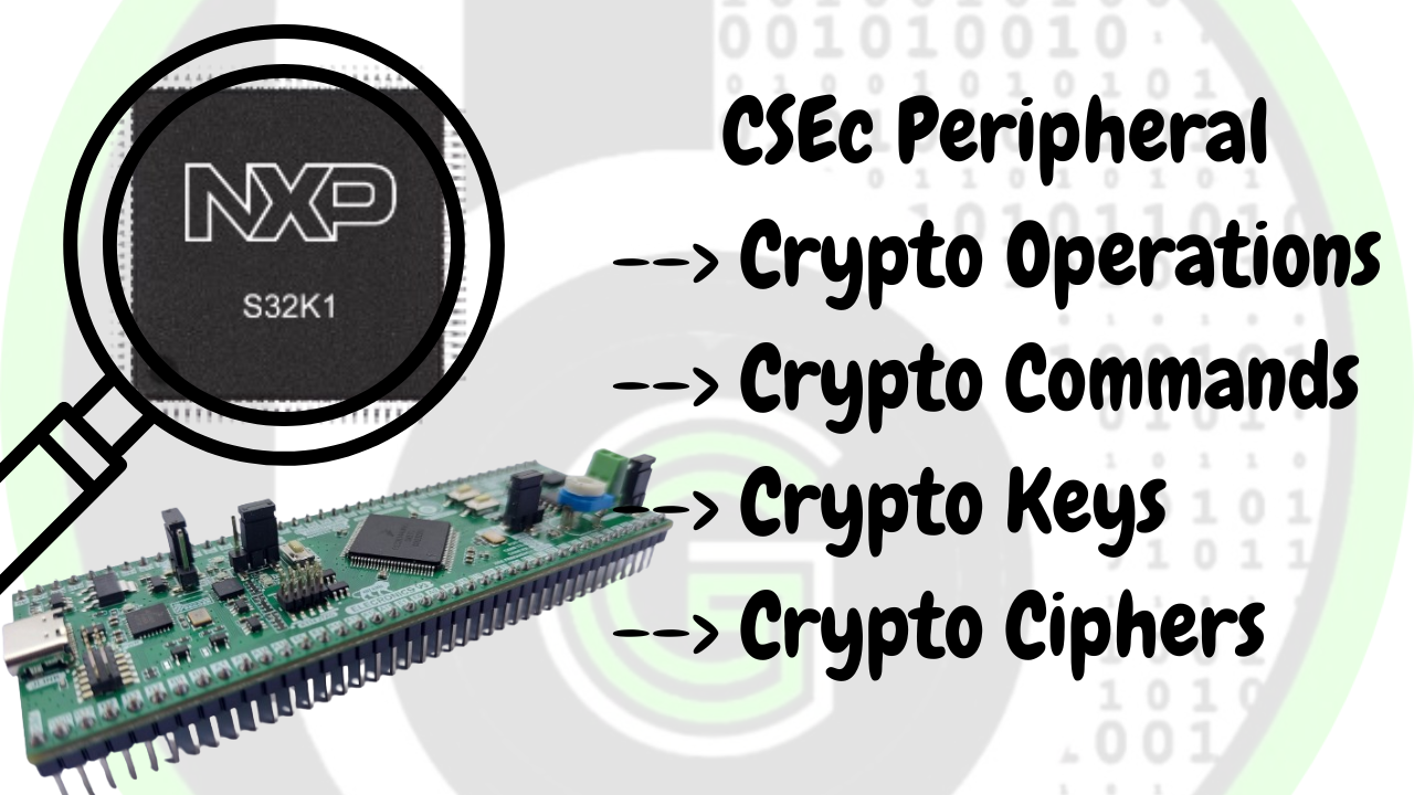
What is CSEc Peripheral CSEc is a microcontroller peripheral in NXP Semiconductors S32K1 series of Automotive MCU’s. CSEc peripheral is a security subsystem, which is based on SHE standard for doing cryptographic operation and establishing secure communication between the ECUs in the car. Security subsystem is a dedicated subsystem within an IC (Microcontroller or SoC) through which we can perform cryptographic operations in microcontroller and protect cryptographic keys from the software attacks. Broadly there are 2 types of security sub-systems in a microcontroller for doing cryptography operations: Secure Hardware Extension (SHE) Hardware Security Module (HSM) The security-subsystem, which we are discussing in this blog: CSEc Module, is based on SHE standard security sub-system. That means using the CSEc peripheral present in S32K144 MCU, we can perform symmetric crypto operations and secure up to 17 user keys. To know more about the SHE standard, refer to this blog. Configuration of CSEc peripheral As CSEc peripheral is SHE standard based security-subsystem and in SHE standard all the controlling of the crypto algorithms and operation’s is done via finite state machine or small CPU core. In S32K1 series, it is done via finite state machine thus the control logic for using CSEc peripheral is command wise. There are commands specified for doing crypto operations according to HIS-SHE specification version 1.1 We just need to specify which command to send, and corresponding crypto operations are executed. (make a graphic showing state machine, she specification and commands with elecronicsv2 and s32k144 photo) The state machine algorithm to use CSEc peripheral is implemented in FTFC module of the S32K1 MCU’s. FTFC is a Flash memory module which is a Hardware IP in S32K1 series of MCU which is used to modify flash memory contents. Flash memory configuration, initialization and all other things are done by FTFC module. Will deep dive into FTFC module in separate blog. For now, to use CSEc peripheral, features have been added to the FTFC module to support SHE functional specification version 1.1. The FTFC module enables encryption, decryption, CMAC generation-verification and algorithms for secure messaging applications. Additional APIs are also available for Secure Boot configuration, True Random Number Generation (TRNG) and Miyaguchi-Prenell compression. The FTFC core takes care of the flash as well as CSEc functionalities. So, to use CSEc peripheral, we need to configure FTFC module. This configuration is flash memory partitioning, we need to partion the flash memory to emulated EEPROM. By doing so, the FTFC module enables encryption, decryption and CMAC generation-verification algorithms for secure messaging applications. The user can configure the FTFC module for emulated-EEPROM operation by issuing a Program Partition Command (PRGPART). The PRGPART command provides flexibility to specify the partition size between emulated-EEPROM operation and normal operations as per user’s wish. To enable CSEc functionality, the device must be configured for emulated-EEPROM operation. The PRGPART command is used to enable CSEc and also provides a mechanism to specify the key size. Depending on the key size, the last 128/256/512 bytes of EEERAM are reduced from the emulated- EEPROM and become un addressable (so as corresponding EEPROM –backup). This storage is secured and utilized to store cryptographic keys. Once the user configures the FTFC module for CSEc functionality and loads the user keys for the security operations, the device is ready for any security related operations as described in the HIS-SHE specifications. //Show practical codes/API and working of flash memeory partionining // understand abput how memory configuration is being done, what size is done and what size is left and which API is used //How to check CSEc peripheral is configured and memory partioning is done. Crypto operation command using CSEc Okay so now once CSEc is being configured and initialized for use now let’s dwell into how to do crypto operations with it. CSEc peripheral uses command-based programming interface. Crypto operations like Encryption, decryption, loading keys, generating keys and etc. all are done via commands. These commands are handled by CSEc PRAM interface. CSEc PRAM interface is a memory area of around 128 bytes. which is divided into 8 sections. Each section is termed as page here. Starting from page 0 to page 7. Each page of 16 bytes. As shown in below pic. So, we send the command by writing it on page 0 according to the command header specified below and with the command some additional information required by that command and in return we get the result on pages 1-7. The Structure of the command header is standard for all the commands, command header is divided into 6 bytes. –> FuncID: Function Identification (ID) field is a 1 bit long and specifies the security command to be executed. Valid from 0x00 to 0x16. In the code enum One can relate CSEc PRAM interface as a Sheet. That sheet is divided into 8 horizontal lines are. Terminologies to refer to these lines is pages. So their are total 8 pages, starting from page 0 to page 7. Now in first page 0, we write the command In the above image, first page Page 0, includes the command header (Page 0, Word 0) and message control length (Page 0, Word 3). The rest of the pages are utilized for input/output data information. Writing to the command header triggers the macro to lock the CSEc PRAM interface and start the CSEc operation. Hence, to setup a CSEc command, the user should first enter data information followed by message length information and must write command header last. Cryptographic Keys in CSEc Lorem ipsum dolor sit amet, consectetur adipiscing elit. Ut elit tellus, luctus nec ullamcorper mattis, pulvinar dapibus leo. Cryptographic ciphers in CSEc Lorem ipsum dolor sit amet, consectetur adipiscing elit. Ut elit tellus, luctus nec ullamcorper mattis, pulvinar dapibus leo. Cryptographic Operations in CSEc Lorem ipsum dolor sit amet, consectetur adipiscing elit. Ut elit tellus, luctus nec ullamcorper mattis, pulvinar dapibus leo. Features of CSEc Peripheral Lorem ipsum dolor sit amet, consectetur adipiscing elit. Ut elit tellus, luctus nec ullamcorper mattis, pulvinar dapibus leo. CSEc Peripheral has following
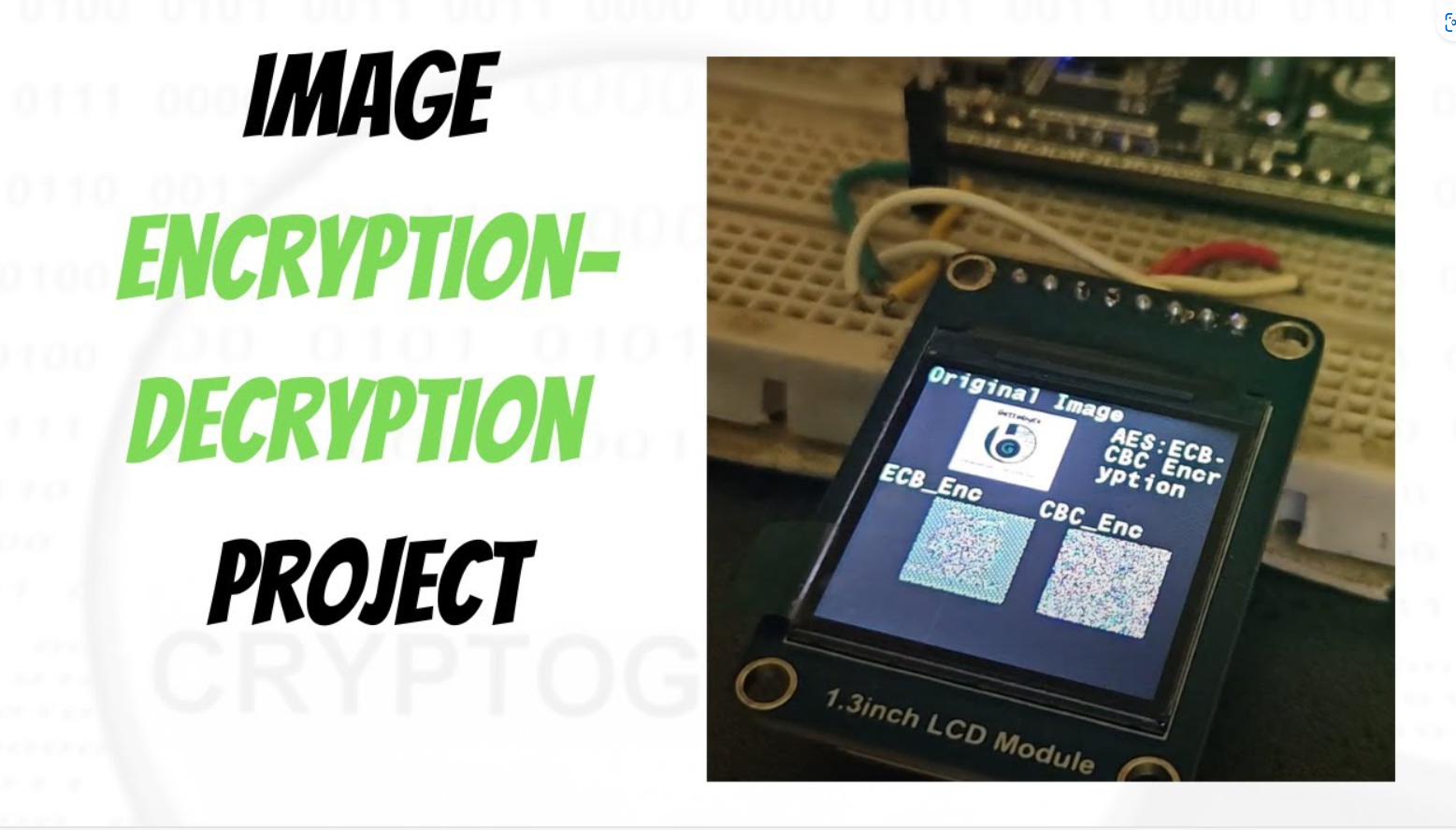
Table of Contents Overview https://gettobyte.com/wp-content/uploads/2023/12/20240211232811.mp4 So, hello guys, welcome back to the gettobyte YouTube channel. The video you have just seen is the encryption-decryption of an image using Microcontrollers. And that’s what we will implement and learn to do in today’s video. We are going to explore, how to use cryptography technology in microcontrollers. Will be doing the hands-on activity for encryption/decryption of data and images using the ElecronicsV2 Development board. Encryption/Decryption is the cryptography concept and what we are going to achieve on doing so is to know how to use cryptography technology through microcontrollers. For doing Encryption/decryption we are using the AES cryptography algorithm, which is supported in the ElecronicsV2 development board through its SHE standard-based CSEc peripheral. For those who are new to the channel and world of cryptography technology, would recommend watching these videos in the following hierarchical order to get an understanding of cryptography and the technical terms that have been stated just now. What is Cryptography How Cryptography is implemented in Microcontrollers Cryptography basic understanding and terminologies DIY Project Statement What i have done here is take an image, which is an original image and convert it into a string of bytes. After that, wrote software to store that string of bytes in the ElecronicsV2 development board and to do encryption through AES cryptography algorithm on the stored data. On successful encryption, those string of bytes are changed to the encrypted format of data and then that encrypted data is processed to print the encrypted image on color LCD Screen. This is just a basic demo on how to use cryptography technology for securing the original data. Here we are printing encrypted image on the LCD Screen, Same way we can send, encrypted image data to other microcontroller via CAN, LIN or any other protocol. Will be doing this activity too in upcoming blogs. Follow this cryptography technology playlist to explore more such demos. Tools needed Now to achieve this, we will be needing some Hardware and Software tools. In Hardware part, we will be needing: 1) ElecronicsV2 Development Board: BuyLink 2) JlinkV9 Debugger: Debugger to program the ElecronicsV2 Board: Buy Link 3) Double Breadboard: 4) ST7789 Color LCD Screen: LCD screen for printing images ElecronicsV2 Development Board JlinkV9 Debugger Double Breadboard ST7789 Color LCD Screen ElecronicsV2 Development Board ElecronicsV2 is a development board built on NXP Semiconductors S32K144 Microcontroller. S32K144 MCU is an automotive Microcontroller based on ARM Cortex M4 Processor and is part of NXP S32 Automotive Microcontroller family. ElecronicsV2 board which is built on S32K144 MCU has a cryptography peripheral present in it, called as CSEc(Cryptography Security Engine). Which is a SHE standard based security sub-system for doing cryptographic operations and establishing secure communication b/w the ECU and the sensors/actuators of the car. We are gonna use CSEc peripheral of S32K144, to do encryption/decryption of data JlinkV9 Debugger JlinkV9 Debugger is a hardware debugging tool, that is used to program and debug ARM cortex-based Microcontroller or Microprocessor. You can buy the JlikV9 from this link. ElecronicsV2 has to be connected to Jlink V9 debugger, so that we can program/debug the board. To know about its connection Double Breadboard Tab Content ST7789 Color LCD Screen ST7789 Color LCD Screen In software we will be needing 1) S32 Design Studio IDE: Which is a Desktop Application for programming S32 Family of microcontroller’s/microprocessor. 2) LCD image converter: Desktop application to convert the image into string of bytes S32 Design Studio IDE LCD image converter S32 Design Studio IDE S32 Design Studio is the IDE that is used for development of Embedded Software Development on S32 family of Microcontrollers. IDE stands for Integrated Development Environment, which is used for doing software development on microcontrollers. ElecronicsV2 board has S32K144 Microcontroller, which is part of NXP Semiconductor S32 family of MCU. Thus, we will be using S32 Design Studio for doing Handson activity with ElecronicsV2 boards, S32 Design Studio: is an Integrated Development Environment to write the microcontroller programs for S32 Automotive Microcontrollers. Install the S32 Design Studio software in your PC and in addition to it user also have to download the Real Time Driver (RTD) package for S32K1 MCU. Refer to this blog for full installation guide of S32 Design Studio step-by-step: Getting Started with S32 Design Studio Part 1 | Gettobyte LCD image converter We will use this software to convert the images into string of bytes. How to use this software is mentioned below: Getting Started Okay so now let’s get started with it, i hope so you guys have gathered all the software/hardware that i have mentioned above and connected all the hardware items. We will at first directly gonna do the practical implementation and then going to dwell deep into it. Now for microcontroller programming on ElecronicsV2, I am making a separate GitHub repo, where all the demo examples and peripherals codes would be committed with time. Clone the repo, into your local PC. Link of the repo: Now in the repo, navigate to: Peripheral Drivers-> CSEc , here you will see different examples related to cryptography technology in ElecronicsV2 Development board.  The CSEc_AES_ENC_CBC_ECB_ST7789, is the project for which demo video is shown to you in the starting of the blog. We are going to execute and understand this project. After cloning the project into your PC, you can see the same folder structure as shown to you at GitHub repo at the path Peripheral_Drivers->CSEc: Now open the S32 Design Studio and we have to open the Project CSEc_AES_ENC_CBC_ECB_ST7789 into it. CSEc_AES_ENC_CBC_ECB_ST7789 is already developed code, so to open it navigate to file->Open Project from File System To know how to open already developed project in S32 Design Studio, refer to this blog: Getting Started with S32 Design Studio Part 1 | Gettobyte. After opening the project, you can see it open in project explorer window of S32 Design Studio. Opening the Cryptography example projects Opening the Cryptography example projects in S32 Design Studio. In this example project you will find