ElecronicsV(S32K144 MCU)
Getting Started Dive into blogs on how to get started with ElecronicsV2. Hardware setup, IDE Software Installation and setup, familiarity

Getting Started Dive into blogs on how to get started with ElecronicsV2. Hardware setup, IDE Software Installation and setup, familiarity
Integration of FreeMaster Software with ElecronicsV3 Board (S32K144 MCU) via UART Driver of Autosar MCAL Layer

How to use FreeMaster with S32 Design Studio

Looking to learn Autosar Software Tech Stack?? Autosar MCAL Layer is the easiest and inexpensive way to start learning your automotive software journey that too with Handson DIY projects and not just theoretical way

S32 Design Studio Code Configurator Tool tutorial and understanding
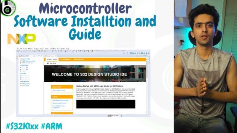
S32 Design Studio IDE Softwrae Installation and SDK installation for S32K144 MCU’s
Get Started with NXP S32K144EVB for Automotive and Industrial Applications. MCU features, Board features, PinOut, SDK and IDE installation with debugging