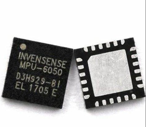
 A MUST HAVE Motion Interfacing one finds in almost every smartphone and tablet. It is a 3-axis gyroscope and 3-axis accelerometer, in total an integrated 6-axis MotionTracking device all in a single small 4x4x0.9mm package. This package size has been achieved by the MEMS (MicroElectroMechanical System) innovation.
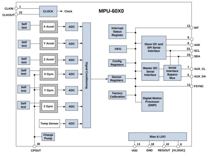
Coming to some technical aspect of the IC,
- It comes with a dedicated I2C sensor bus at 400KHz
- Features 3 16-bit analog-to-digital converters (ADC) each for digitizing gyroscope and accelerometer outputs.
- Gyroscope full-scale range of 250,500,1000 and 2000 degree/sec (DPS).
- Accelerometer full-scale range of 2g,4g,8g,16g and
- On-chip 1024 Byte FIFO buffer which enables the system to read the sensor data in burst and then enter the low-power mode.
- Lastly, it operates at a power supply voltage range of 2.375V – 3.46V.
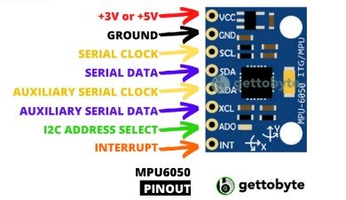
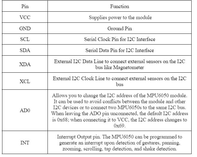

A two wire, half duplex interface comprising Serial Data SDA and Serial Clock SCL, I2C lines are in general open-drain and bi-directional.
It is a master slave implementation where the master puts the slave device address on the bus and salve with the matching address acknowledges the master.
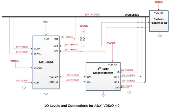
Here the MPU-6050 operates as a slave device when communicating with the MCu and the SDA and SCL lines are pulled up to VDD. The maximum bus speed is 400kHz.
The slave address of the MPU-6050 id 0b110100x, a 7-bit long. Here the LSB bit i.e.x in the 7-bit long address is determined by the logic level at AD0 pin.If x=0 i.e., pin AD0 is Logic LOW otherwise Logic HIGH.
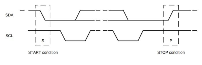
The I2C communication begins and ends with the START and STOP COndition respectively. Whenever the master puts the Start condition on the bus the communication is established and as long as the Stop condition is sent by the master
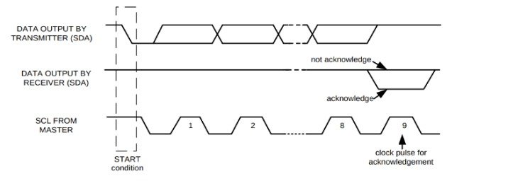
The transaction of HIGH too LOW for the SDA pin keeping the SCL pin HIGH is marked as the Start condition.
The transaction of LOW too HIGH for the SDA pin keeping the SCL pin HIGH again is marked as the Start condition.
The data format of the I2C is 8-bit long. The transmission byte is followed by the acknowledge signal (ACK) shock clock generated by the master. The slave sends the ACK signal by pulling the SDA down and holding it during the HIGH portion of the acknowledged clock pulse.
If a slave is busy and cannot transmit or receive another byte of data until some other task has been performed, it can hold SCL LOW, thus forcing the master into a wait state. Normal data transfer resumes when the slave is ready and releases the clock line.
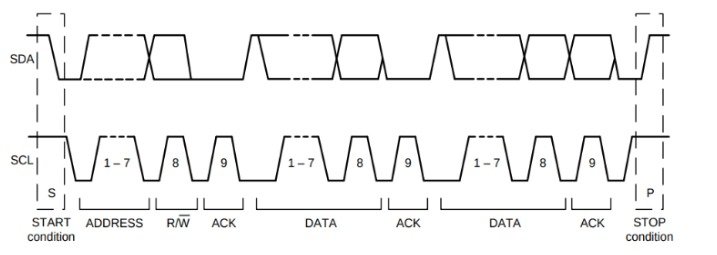
Coming to the communication part, the master first sends the Start condition followed by the 7-bit address with 8th bit being read/write bit. The read/write signifies whether the master wants to read the data or to send the write command. The 9th clock pulse consists of the ACK or NACK (not Acknowledged) signal. The data transmission is terminated by the Stop Condition.
Interestingly the master can send Start condition and address to slave without first generating the Stop condition. 
For Writing the internal MPU-6050 register, the master first sends the Start Condition followed by the slave address and writes bit 0. At the 9th clock pulse, the slave sends the ACK signal. Seeing ACK, master sends the register address to the bus on whose data master wants to write which is again followed by the ACK signal from the slave. After that the master puts the register data on to the bus. The communication eds with the Stop Condition sent by the master.
To write multiple bytes after the last ACK signal, the master can continue outputting data rather than transmitting a stop signal. In this case, the MPU-60X0 automatically increments the register address and loads the data to the appropriate register.

To read the internal MPU-60X0 registers, the master sends a start condition, followed by the I2C address and a write bit, and then the register address that is going to be read. Upon receiving the ACK signal from the MPU-60X0, the master transmits a start signal followed by the slave address and read bit. As a result, the MPU-60X0 sends an ACK signal and the data. The communication ends with a not acknowledged (NACK) signal and a stop bit from the master. The NACK condition is defined such that the SDA line remains high at the 9 th clock cycle. 

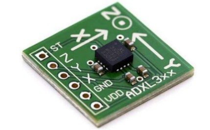
The ADXL335 (Adafruit Industries) is a thin, small, low power, complete 3-axis accelerometer with signal conditioned voltage outputs. It measures acceleration with a minimum full-scale range 3g. This device measures the static acceleration of gravity in tilt-sensing applications and dynamic acceleration resulting from motion, shock, or vibration. The ADXL335 contains a polysilicon surface micro machined structure built on top of a silicon wafer. Polysilicon springs suspend the structure over the surface of the wafer and provide resistance against acceleration forces. A differential capacitor, consisting of independent fixed plates attached to the moving mass, measures the deflection of the structure. Acceleration unbalances the capacitor, which, in turn, results in a sensor output with amplitude proportional to the acceleration experienced.
Adding a 3-axis magnetometer to a 3-axis accelerometer and a 3-axis gyroscope

will obtain a 9-axis inertial measurement unit (IMU) sensor which provides 9DoF plus roll, yaw, and pitch information during motion and orientation of the hand. Magnetic field sensor is a small-scale microelectromechanical systems(MEMS) device for detecting and measuring magnetic fields (Magnetometer). According to InvenSense, “Gyro noise performance is 3× better, and compass full-scale range is over 4× better than competitive offerings.” The MPU-9250 uses 16-bit Analog-to-Digital Converters (ADCs) for digitizing all nine axes, making it a very stable 9 Degrees of Freedom (DoF) board.