Over 10 years we help companies reach their financial and branding goals. Engitech is a values-driven technology agency dedicated.

Gallery

Contacts

411 University St, Seattle, USA

engitech@oceanthemes.net

+1 -800-456-478-23

Getting Started S32 Automotive Platform S32K1 Tech

ElecronicsV2: Arduino for Automotive DIY Projects

Table of Contents

Overview

In an era, where the automotive sector is at its prime and everyone desires to make their career advancements in the Automotive field, there is a need for a Microcontroller based development board that is of automotive grade, with automotive capabilities to do hands-on learning and gain knowledge on automotive skill sets. And in such a world, ElecronicsV2 boards make a grand entrance.

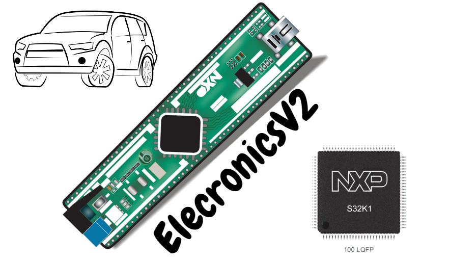
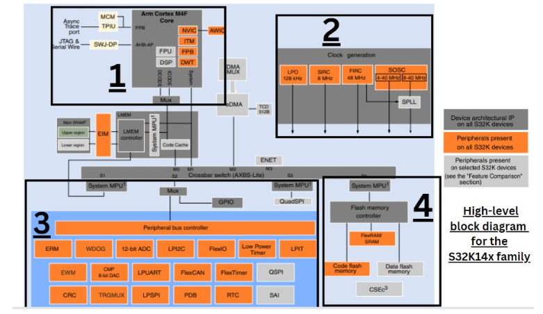
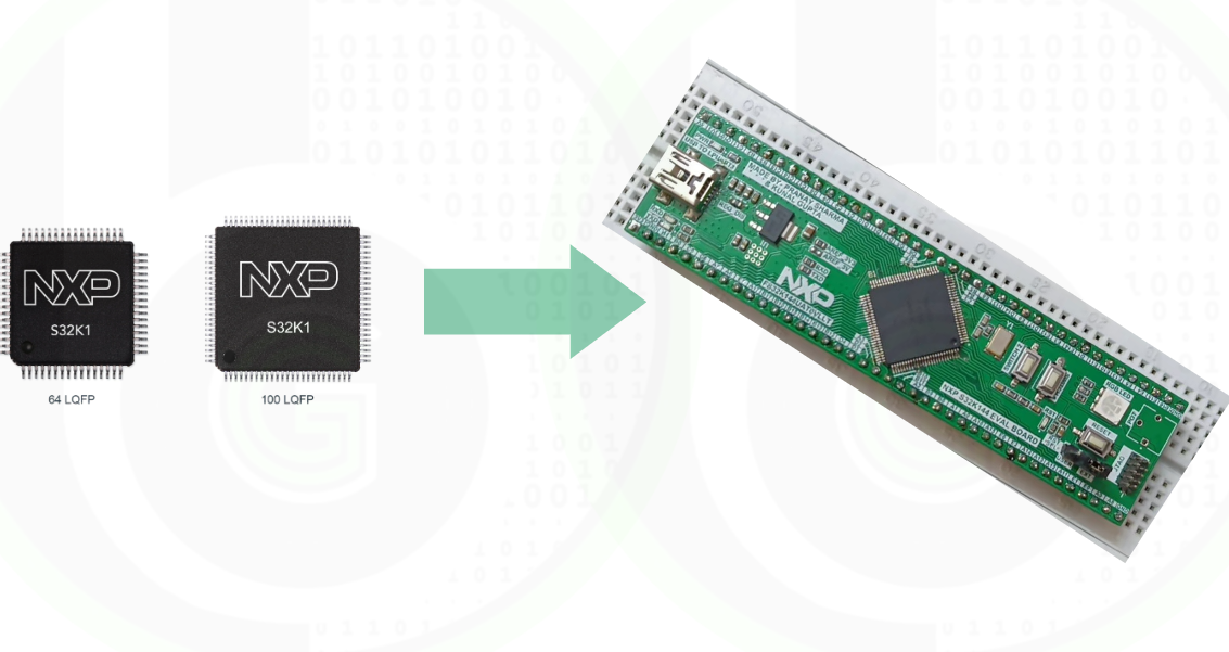
ElecronicsV2 is a development Board based on NXP Semiconductor S32K144 MCU. The development board has a rich set of onboard features and interfaces to make Automotive DIY projects. It is powered with S32K144 MCU, which is based on ARM Cortex M4 Core with Automotive peripherals like CAN, LIN, FlexIO, SAE-J2602, Half HSM, and advanced Timer peripheral.

ElecronicsV2 is not just a development board for Automotive, but it is also a prime candidate for students, working professionals, and hobbyists to learn embedded projects and learning in an industrial Microcontroller out of Arduino and ESP environment. ElecronicsV2 is based on the S32K144 Microcontroller.

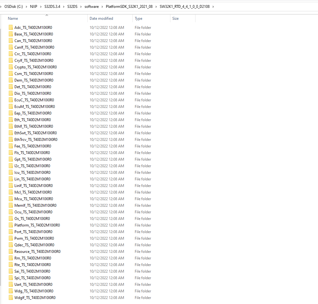
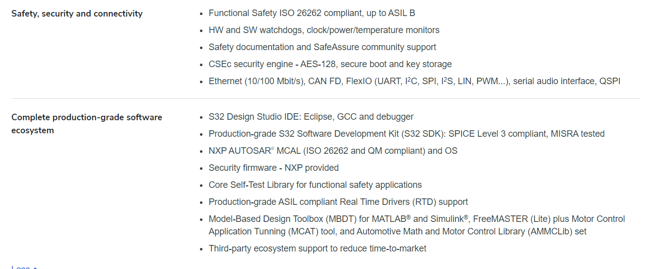
S32K144 MCU is part of the S32 family of microcontrollers, for which NXP semiconductors provide a dedicated IDE for embedded software development and SDK for embedded application development. What makes the S32K144 apart, is its availability of SDK with Autosar standard!! Students and working professionals can do Autosar-based and hands-on learning using the Autosar MCAL SDK. All of this is possible/done via the ElecronicsV2 board.

Elecronics V2 Development Board

Elecronics V2: is a development board that is designed based on NXP Semiconductors S32K144 MCU by Gettobyte Community.

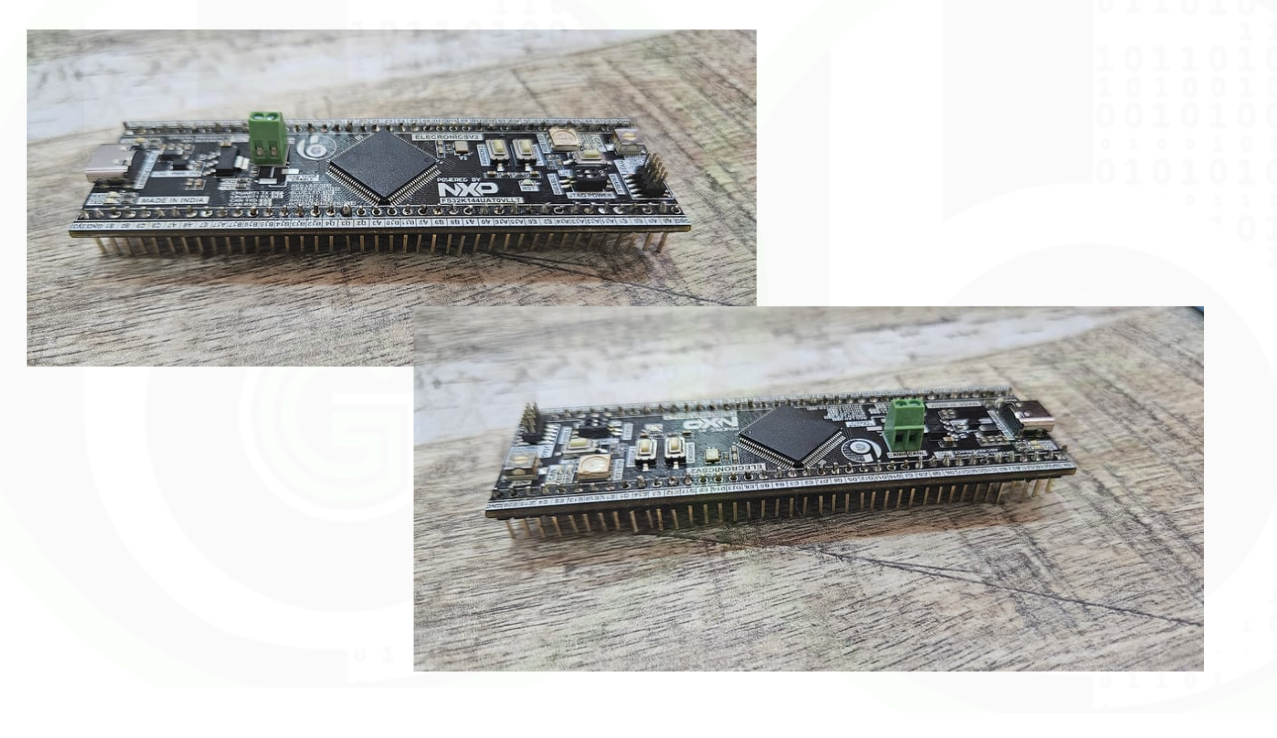
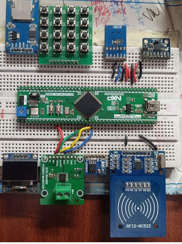
ElecronicsV2 is a breadboard-compatible board, which has all Input/Output pins exposed via male headers and can be expanded by embedding it into the breadboard for easy use and development. S32K144 microcontroller can be used for various industrial projects like Automotive, Industrial Automation, consumer electronics, and IoT. This board is cost-effective as compared to the original evaluation board of S32K144.

ElecronicsV2 Development Board

Documentation on ElecronicsV2 Board: User Manual of ElecronicsV2 Board

Getting Started with ElecronicsV2 Board: Getting started with ElecronicsV2 Board

…………………………………..

The major challenge people face is a lack of resources or scattered content to learn and do hands-on such Industrial microcontrollers. For learning the Embedded basics and firmware development on this board, viewers can refer to the tutorial blog series on the S32K144 microcontroller. Refer to this link for more info. 

S32K144 Content and Resources

Features of ElecronicsV2 Development Board

ElecronicsV1 is breadboard compatible development based on NXP Semiconductors S32K144 MCU. Which has following features:

Features of ElecronicsV2

Their are 2 Best Things about the design of the ElecronicsV2 Board:

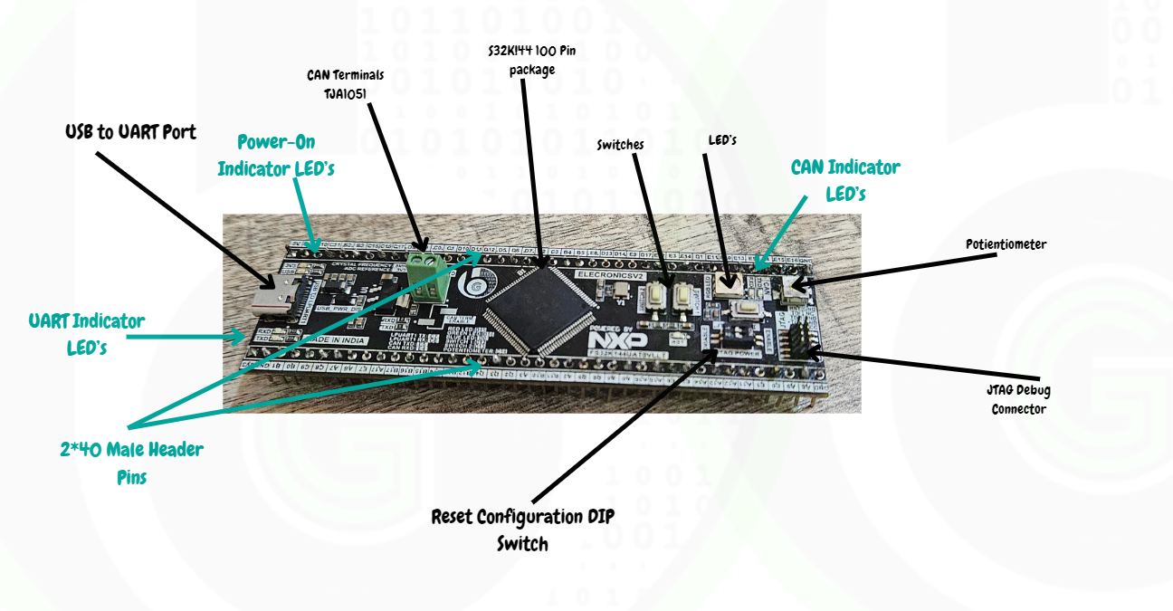
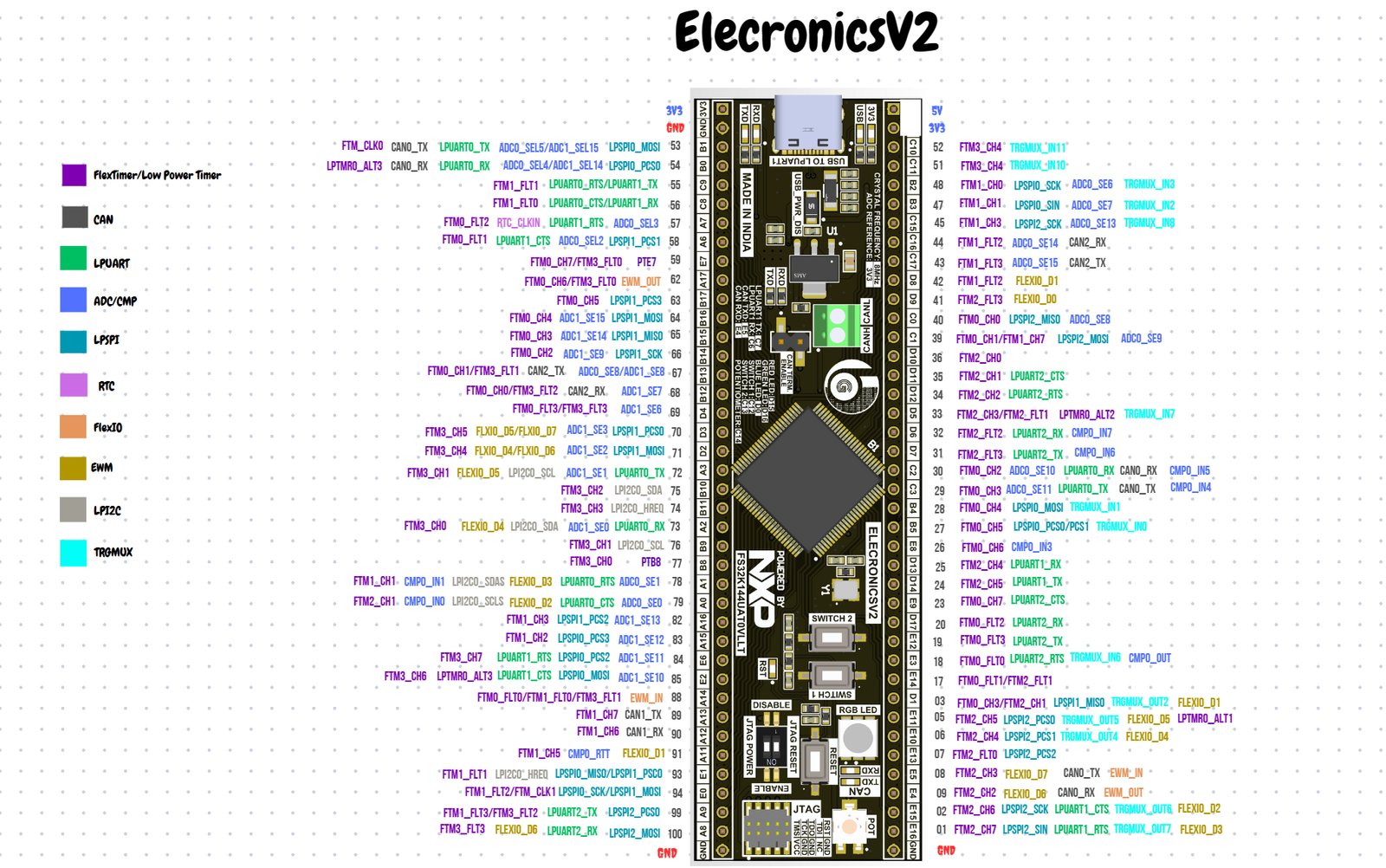
  1. First is 2*40 male header pins, which exposes all the pins of the Microcontroller and it can be easily connected to a number of sensor/modules with neat and clean connections
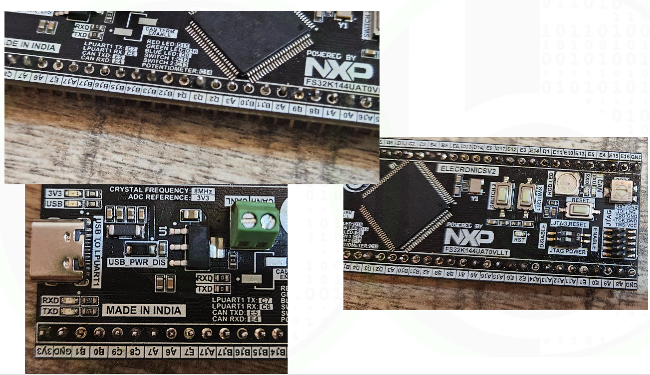
  2. Another thing is the silkscreen present on the board. On the ElecronicsV2 you can see there is pin labeling for all the features present on the board, which makes it easy for users to do development on the board, instead of seeing pinouts/schematics again and again.

Pinout of ElecronicsV2

About S32K144 MCU

Refer to this blog, to know indepth features and specs of the S32K144 MCU:

Reasons for starting your journey with S32K144 MCU as students/hobbyiest

  1. The most important reason for selecting this microcontroller is it has Software stack/drivers for S32K144 MCU with Autosar complaint MCAL Layer, which will help students learn about Autosar at the college level using ElecronicsV1 by making DIY projects just like on Arduino. Autosar is one of the highly demanded skills set in embedded and automotive industry.
  2. S32K144 MCU has many Automotive communication protocols like: CAN, LIN, FlexIO, Motor control-based TIMER Peripheral, CSEc Hardware Security Module to implement Cryptography Application. So using this board will give students understanding and hands-on industrial level knowledge of automotive/embedded field.
  3. Based on ARM Cortex M4 processor running at 112MHz, students can explore and learn about ARM technology by doing hands-on via this controller and using its IDE: S32DS.

Debugger/Programmer

The board doesn’t have on-board debugger, so it has to be programmed using external debugger like: J-Link Debuggers or PEmicro OpenSDA debugger.

Original Jlink debugger and PEmicro debugger comes very expensive, so best and reliable alternate to those debuggers i to buy JLink V9 Debugger Emulator – ARM MCU Development Tool,  which comes at a cost of 2.5K around and using this debugger you can debug any ARM cortex M3/M4 chip. More details and how to use this debugger is here.

JlinkV9 Debugger is Chinese clone of the original Jlink Base Debugger which is best to use by students/hobbyists and affordable too.

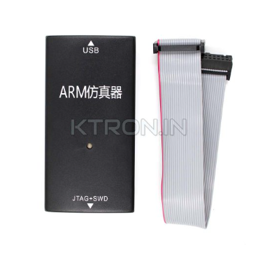
Viewers can buy the debugger from here: Buy JLink V9 Debugger Emulator – ARM MCU Development Tool – KTRON India.

It comes at a cost of 2.5K around. Buying this debugger once and then it can be used with any ARM Cortex M based Microcontroller.

Other alternative for debuggers:

Target Audeince for the board

Audience for ElecronicsV2 Board

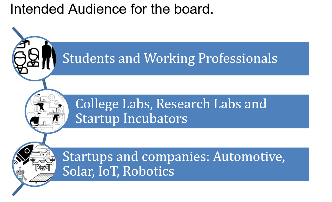
The board can be used by variety of audience and applications as follows:

  • It can be used by students and practise enginners for learning Embedded systems on Industrial Microcontrollers like that of NXP Semiconductors to come out of Arduino and ESP environment and making DIY projects for different Industries, giving them industrial exposure and skillsets. Thus, this microcontroller is perfect start for students to get hand-on exposure on industrial technologies. 
  • Not only for DIY projects but this board can be used for fast prototyping and development by automotive/EV based startups/companies for their product development. As S32K144 MCU is ARM cortex M4 based and has rich set of peripherals with automotive certified standards for developing products for body & control, powertrain and electrification domains of the car.

Buy the board

The board is priced at INR 4,999(Excluding GST and Shipping Charges).

For college students, ElecronicsV2 is of 2,999. For students, there is a  discount of INR 2000. They have to submit their student ID and government ID, after the verification from our end, their order will be processed.

The Kit will include, Jlink V9 debug Users can buy from above link:

  1. One ElecronicsV2 Development Board
  2. JTAG-SWD Debug Adaptor
  3. 10 Pin JTAG debug connecting wire

Getting Started with Board

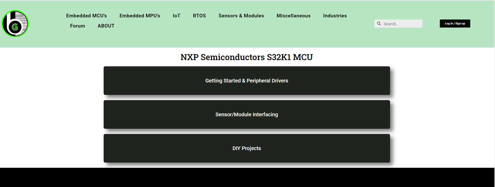
For using the S32K144 MCU, NXP semiconductors provides S32Design Studio IDE and S32K1 Software Package. S32K1 Software package has all the peripheral drivers, example codes, middleware stacks for starting development/learning on S32K144 MCU. on Refer above video to get started with ElectronicsV1 board and how to setup S32K144 SDK.

Further viewers can refer to blog series on S32K144 MCU, to do hands-on learning on all of its peripherals and then do sensor-module/DIY Projects interfacing with using ElecronicsV1 board.

Chronological order to start with this board:

  1. Getting Started with S32Design Studio.
  2. Getting Started with Elecronics V1: S32K144 MCU Development board.
  3. Peripheral driver tutorials on ElecronicsV1.
  4. Sensor/Module Interfacing with ElecronicsV1.
  5. DIY projects using ElecronicsV1.

Tigger MUX Control(TRGMUX) Peripheral in S32K144 MCU

What is TRGMUX peripheral? TRGMUC provides an extremely flexible mechanism for connecting various trigger sources to multiple pins/peripherals. The trigger multiplexer (TRGMUX) module allows software to configure the trigger inputs for various peripherals.   The TRGMUX module allows software to select the trigger source for peripherals.   TRGMUX is a peripheral which provides mechanisms for connecting various trigger sources to multiple pins/peripherals. Each peripheral that accepts external triggers usually has one specific 32-bit trigger control register. Each control register supports upto 4 triggers and each trigger can be selected from available trigger sources.   Author: Kunal Gupta

Read More »

PDB (Programmable Delay Block) Peripheral in automotive microcontroller (NXP S32K144)

What is Programmable Delay Block(PDB) peripheral? PDB provides controllable delays from either an internal or an external trigger, or a programmable interval tick, to the hardware trigger inputs of ADCs. PDB can also provide pulse outputs that are used as the sample window in the CMP block.   The PDB contains a counter whose output is compared to several different digital values. If the PDB is enabled, then a trigger input event will reset the PDB counter and make it start to count. A trigger input event is defined as a rising edge being detected on a selected trigger input source, or if a software trigger is selected and the Software Trigger bit (SC[SWTRIG]) is written with 1 Author: Kunal Gupta

Read More »
CAN Bit TIming
Automotive Protocols
Rohan Singhal

CAN Bit Timing Explained

Bit timing in CAN is all about ensuring that every node on the network can correctly interpret the bits being transmitted. This synchronization is crucial for maintaining the integrity and efficiency of data communication. Bit Segmentation Each bit in a CAN frame is divided into several segments: Synchronization Segment (Sync_Seg): This is the part where the actual synchronization occurs. It’s always one-time quantum (TQ) long and helps align the clocks of all nodes on the network. Propagation Segment (Prop_Seg): This segment compensates for the physical delay in signal propagation across the network. Phase Segment 1 (Phase_Seg1): This is used to compensate for edge phase errors by lengthening the bit time if necessary. Phase Segment 2 (Phase_Seg2): Similar to Phase_Seg1, but it shortens the bit time if necessary. Each of these segments is made up of a certain number of time quanta (TQ), which are the smallest time units in a CAN network. Sample Point The sample point is a critical point within the bit where the bus level is read and interpreted as a logical value. Here’s why it’s so important: Accurate Bit Reading: The sample point is where the CAN controller reads the bit value. It is crucial to set the sample point accurately to minimize errors due to signal noise or other disturbances on the bus. Preferred Value: Typically set at 87.5% of the bit time, this value is preferred by protocols like CANopen and DeviceNet. This means that the bit is sampled after 87.5% of its duration has passed. Adjustable Range: The sample point can vary from 50% to 90% of the bit time, allowing flexibility depending on the network requirements and conditions. For example, ARINC 825 uses a default value of 75%. Noise Minimization: Setting the sample point correctly helps in minimizing the impact of signal noise. Sampling too early or too late can lead to incorrect bit interpretation, especially in noisy environments. Understanding Bit Rate and Bit Timing Bit Rate The bit rate in CAN communication refers to the speed at which data is transmitted over the CAN bus, typically measured in bits per second (bps). The bit rate is a crucial parameter because it determines how quickly data can be sent and received between nodes on the network. Common bit rates in CAN systems include 125 kbps, 250 kbps, and 500 kbps, with some systems operating at even higher speeds, such as 1 Mbps. Bit Timing Bit timing in CAN communication is the precise control of the duration and positioning of each bit transmitted on the bus. Proper bit timing ensures that all nodes on the network sample the bits at the same point, leading to accurate and synchronized data transmission. Bit timing is divided into several segments within each bit time, which collectively ensure robust and reliable communication. How Bit Timing Ensures Synchronization To maintain synchronization, the CAN controller can adjust the length of a bit by an integral number of time quanta (TQ). The maximum value of these adjustments is termed the Synchronization Jump Width (SJW). Hard Synchronization: Occurs on the recessive-to-dominant transition of the start bit. The bit time is restarted from this edge. Resynchronization: Occurs when a bit edge doesn’t occur within the Sync_Seg in a message. One of the Phase Segments is shortened or lengthened, depending on the phase error, up to the SJW. Factors Affecting Bit Rate Four primary factors influence the CAN bit rate: Oscillator Tolerance: Variations in the oscillator frequency can affect the timing accuracy. High-precision oscillators are essential for maintaining a stable bit rate. Propagation Delay: The physical length and quality of the CAN bus can introduce delays. Prop_Seg is adjusted to compensate for these delays. Network Load: Heavy network traffic can lead to delays and timing issues. Proper network design and bit timing configuration help mitigate these problems. Bus Length: Longer bus lengths introduce more propagation delay, requiring adjustments in the Prop_Seg to maintain synchronization. Prescaler Division The prescaler is used to divide the clock frequency to generate the required clock frequency for CAN. For example, if the clock frequency is 48 MHz and we need an 8MHz CAN clock, the prescaler value would be 6. How the Prescaler Division Works Clock Frequency: The original clock frequency provided by the oscillator. Prescaler Value: The value by which the original clock frequency is divided to achieve the desired CAN Clock Frequency. IMPORTANT The CAN system clock is chosen so that the desired CAN bus Nominal Bit Time (NBT) is an integer number of time quanta (CAN system clock periods) from 8 to 25. Time Quanta Definition: The time quantum (tQ) is the basic time unit in CAN bit timing. It is derived from the CAN system clock divided by the prescaler. Calculation: For example, if the CAN system clock is 48 MHz and the prescaler is set to 6, then: Nominal Bit Time (NBT) Definition: The Nominal Bit Time (NBT) is the total duration of a single CAN bit, measured in time quanta (tQ). It is the sum of the time segments within a bit period: Sync_Seg, Prop_Seg, Phase_Seg1, and Phase_Seg2. Components: Sync_Seg: The synchronization segment, always 1 tQ. Prop_Seg: The propagation delay segment, compensates for the signal propagation delay. Phase_Seg1: The first phase segment, can be adjusted to resynchronize the clock. Phase_Seg2: The second phase segment, also adjustable for resynchronization. Calculation: Practical Example of Bit Timing Calculation For calculating Bit Time and Segmentation, some important parameters are taken into account before starting the calculation. Parameters: Bit rate MCU Clock/Oscillator Frequency Bus length Bus propagation delay Propagation delay of TxD plus RxD offered by CAN Transceiver But, usually, values like total propagation delay offered by CAN transceiver, Bus length, and Bus propagation delay, are pre-defined values in their hardware datasheet. Question: Conclusion Understanding CAN bit timing and how the bit rate is adjusted is crucial for ensuring reliable communication in a CAN network. By properly configuring the timing parameters and taking into account factors like oscillator tolerance, propagation delay, network load, and bus length,

Read More »

Add Your Heading Text Here

Kunal Gupta
Author: Kunal Gupta

Author

Kunal Gupta

Leave a comment

Stay Updated With Us

Error: Contact form not found.

      Blog