


Table of Contents So hello guys, welcome back to Gettobyte Once again. Todays blog is going to be on interfacing the Energy metering IC : HLW8012 which is manufactured by HLW Technology.On previous blogs we have developed the application driver for W25Q SPI based flash memory’s, is time we are going to develop the Application driver for HLW8012. So first question that must come in your mind is that what is Energy Metering IC. Lets first Understand this term. What are Energy Metering Integrated Chips ? Before Understanding Energy metering IC’s their is one term that i would like to get familiar my viewers that is ASIC’s. ASIC’s are Application Specific Integrated Chips i.e. chips which are designed, developed and fabricated for particular applications.  Energy Metering IC’s are one of the ASIC’s. In this case the specific application is that of Electrical Energy Measurement. By the use and emergence of Energy Metering IC’s we can calculate the Electrical Energy parameters like RMS/Instantaneous Voltage, RMS/Instantaneous Current, Reactive/Active/Apparent Power, Energy Consumed, Power loss/dissipation, Power factor, Frequency digitally. Using this electrical Energy Measurements only our monthly electrical energy bill is calculated. These electrical energy parameters play very important role for monitoring and analyzing of Power consumption in our homes, offices, factories, city’s and all such infrastructures where their is use of electricity. These Ic’s are widely used in Energy Meters, Multifunction Meters, Smart Energy meters, Solar Energy control panels, Factory Automation Panels and etc. Energy metering IC’s are designed using the knowledge of ADC, Opamps, Low pass/High pass filters, use of Analog Electronics with Power Electronics, DSP(Digital Signal processing), Signal Conditioning circuits. All these circuits are designed inside the Energy Metering IC’s using VLSI/VHDL. That is where the concept of Application Specific comes in. So when reading the datasheet of Energy Metering IC’s some overview about these terms and terminologies would be beneficial for understanding the functioning of these IC’s. Voltage and current drive the world in every sense. Using these 2 parameters we can calculate all other electrical energy parameters be it reactive power, active power, energy, frequency, power factor and etc. Energy Metering IC’s primarily measures/senses only Voltage and Current by the use of Signal conditioning circuits, ADC, Opamps, Analog Electronics. Further these IC’s calculates all other Electrical energy parameters using DSP, Low pass/High pass filters and etc. All of these things are designed inside the Energy metering IC’s. Input voltage and current to these IC’s are fed depending upon the principal which we are using for sensing Voltage and current. After feeding the Input to these IC’s via one of the above principals, comes the role of above mentioned circuits/units which are designed inside the chips for their efficient functioning and digital accurate readings. Energy metering IC’s which are widely used are of The above listed metering IC’s and their development boards are very expensive, so for my use case i have found out some cheap/alternative Energy Metering IC’s, but their manufacturer are Chinese companies: STMicroelectronics Metering ICSTMP32/33/34 seriesClick HereTexas Instruments Metering ICsClick HereAnalog DevicesADE seriesClick HereNXP semiconductorsClick Here Previous Next HLW8012( the one we are using this blog) HLW8032 BLO937 PZEM-004T module CS5460 bi-directional energy meter module This is the First string, Second string, Third string of the sentence. General Description of HLW8012 Energy Metering IC HLW8012 is a single phase energy metering IC, which is based on shunt resistor based principal. The HLW8012 module has on board 1 milli-ohm copper-manganese shunt resistor, which acts as a shunt resistor and used to sense the voltage and current. One of the biggest problem with IC, is its datasheet. The datasheet of this IC is in Chinese language, so likely it would be difficult to understand from it. The IC can measure the RMS Voltage, RMS Current, Active power and Outputs these reading digitally in the form of PWM signals. HLW8012 is a good choice for making small and hobbyist kind of projects which requires the measurement of AC electrical parameters. One such project/product that I found, is made on HLW8012. HLW8012 is inexpensive and good alternative to be used in comparison to other expensive metering IC’s. The module of HLW8012 is very handy and easy to use. It has 4 input terminals: 2 terminals are connected with AC Load and other 2 terminals are connected with AC Power supply. HLW8012 Outputs the Readings of Voltage, Current and power via PWM signals of 50 percent duty cycle, Their are two pins in HLW8012 CF and CF1 which outputs the voltage, current and power readings in a digital PWM square signal, which host MCU can capture using Timer Input Capture mode. The readings are directly proportional to the Frequency of the PWM signal. Every modern MCU has Timer peripheral, which we can configure in Timer Input capture mode. In this mode Host MCU can capture the PWM signals from external world (here our external world is HLW8012). That’s how HLW8012 will communicate with the Host MCU. Features of HLW8012 Energy Metering IC Based on shunt resistor based principal. Can measure current upto 20Amps and Voltage upto 300 Volts Easy interface to Host MCU sends voltage, current and power readings digitally via PWM square signals. Needs +5 volt to operate the IC. Block Diagram of HLW8012 Metering IC PINOUT of the HLW8012 Energy metering IC Pin Number 1 Pin number 1 is VCC (Chip Select), which is used to operate the power the HLW8012 IC. Connect this pin to +5 Volts of the host MCU. Pin Number 2 & 3 Pin number 2 &3 are V1P/V1N, which are Current differential input pins. These pins are connected in parallel to the shunt resistor(See the application circuit below). This connection is already made on the Module of HLW8012. The maximum voltage that can be input to these pins are 43.75mV. Pin Number 4 Pin number 4 is V2P, which is Voltage differential input pin, this pin is connected to input AC voltage via resistor network of 47k ohms Pin Number 5 Pin
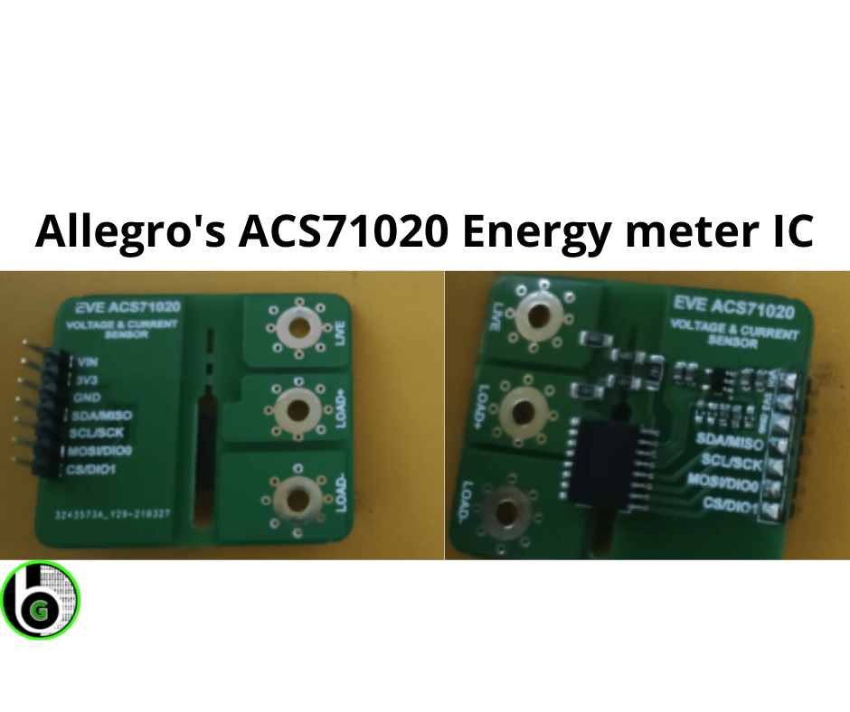
In many applications, we want to monitor AC electrical parameters like Solar chargers, motor control, Battery Charging stations, or Smart energy meters. Measurement of AC current and voltage, by the means of the electronics, is a quite tricky part, unlike traditional electromechanical systems. Below is a basic block diagram to know about it. AC voltage and current signals are first steps down to low voltage and current values.One can not feed High AC electrical voltage and Current signals which can range from 0-1000 units and are even larger than that, in some applications(Power systems, AC motors and etc) to the electronics and digital world. So at first by the use of one of the below listed three methods AC signals are brought to low values( 0-10V, 0-5A) Use of Current Transformer, Potential Transformer, or Rogowski coil. Use of shunt resistors. Use of Hall effect-based principal for current measurement. The signals which we get after processing from these methods are fed into the Digital System where there are signal conditioning circuits, data acquisition circuits, digital signal processing by the use of Digital and Analog Electronics. The Digital System part is designed to embedded into the Integrated chips(ASIC) which are specially designed with the purpose of Energy Metering application. For the digital computation of key electrical parameters like Power factor, Active power, reactive power, Vrms, Irms and etc. Using these key parameters we can monitor the AC electrical parameters through serial interfaces like SPI/I2C with Host MCU. ACS71020 Energy Metering IC Allegro microsystem\’ AC power monitor module ACS71020 is a Single-phase energy monitoring IC that works on the principle of the HALL effect sensing technique (To know about ways to measure current refer to this blog) to measure the AC current and resistor divider network to measure the input AC voltage. It calculates the key electrical parameters using its Metrology Engine and digital system from which it sends the data to the host MCU via I2C and SPI interfaces. The Voltage and current reading that we get from AC voltage and Current measurement blocks via the sense amplifiers are analog in nature. The analog signals from respective Voltage and Current blocks are then fed into the internal ADC\’s(Analog to Digital converter). ADC samples the current and voltage channels at high frequency and then digitally converts them by filtering and decimating the output signal from sense amplifiers to avoid large anti-aliasing filters. The digital word from the ADC is 16 bits for both the current and voltage, which is fed to the digital system for further calculation of other electrical parameters. Its Key Features are: Without the need for any Transformer, Rogowski coils, oversized current transformers, or the power loss of shunt resistors one can calculate Vrms and Irms up to 517V and 90A respectively It has an advanced digital system with galvanically isolated current sensing technology which achieves reinforced isolation ratings in a small PCB footprint Apart from the calculation of Electrical Key parameters it also has many extra features too which are essential for monitoring purposes. ACS71020 IC Pinout Diagram and Pins description ACS71020 IC has 16 pins, Starting from Pin 1-8 are current channel pins, out of which pins 1-4(Fused internally) are all IP+ and pins 5-8(fused internally) are all IP-. Pins 16-15 are Voltage measurement pins ACS71020 IC Schematic For using ACS71020 for typical applications its schematic is pretty easy and less complicated in oppose to other metering IC\’s(STMP32 & ADE series). ACS71020 can be powered directly from the same supply as the system\’s MCU, through its reinforced isolation technology it does need multiple power supplies to power it up. So Vcc and GND pins are connected directly to MCU Vcc and GND pins. I2C pins are at a high level(5V or 3v3), before the start of the I2C Serial Communication, thus SDA and SCL lines are connected with a pull-up resistor. When using in I2C mode, pins 9 & 10 act as DIO_1 and DIO_0( Digital Input/Output) respectively, which are connected directly to MCU Digital Pins( Will get in detail about DIO pins in a later section) For SPI communication, MOSI, MISO, CE pin are at a high level and CLK is at GRND before the start of SPI serial Communication. When using in SPI mode, pins 9 &10 are used as MOSI and CS pins. ACS71020 IC measures the Current and voltage of the input AC signal to calculate all other key parameters. So for inputting the AC voltage & current signals to the ACS71020 IC we will focus on Voltage channel pins(VINP & VINN) and Current channel pins(IP+ & IP-). One thing to recall is that in a single-phase AC supply there are two terminals: Live Wire (Black/Red) carries electricity from the power supply and takes it to the load. Neutral wire(Blue wire) returns the electricity from the load to the power supply to make the circuit complete. VINN &VINP are terminals from where AC voltage is measured, so resistor network divider of 1mega ohm and shunt resistor is made in b/w the VINP and VINN terminals to fit the input AC voltage within the Range of the differential voltage input buffer of ACS71020( +-275mv) as specified in electrical characteristics of the datasheet. IP+[1:4] & IP-[5-8] pins are terminals for AC current measurement. IP+ terminals are fused internally and are connected to a neutral wire of load and IP- terminals are also fused internally and are connected to a neutral wire of supply to complete the current loop of the current channel. EVE ACS71020 Module For doing the practical demonstration with ACS71020 IC we are going to use the EVE ACS71020 breakout board, which is manufactured by the Evelta. The module is cheap and can be used easily with HOST MCU via I2C or SPI communication. The module has pull-up resistors of 10k ohm placed with SDA and SCL pins( pins 12 & 11) of ACS71020 and no pull-up resistors are connected with MOSI and CS pins(pins 10 & 9) means we can use these