
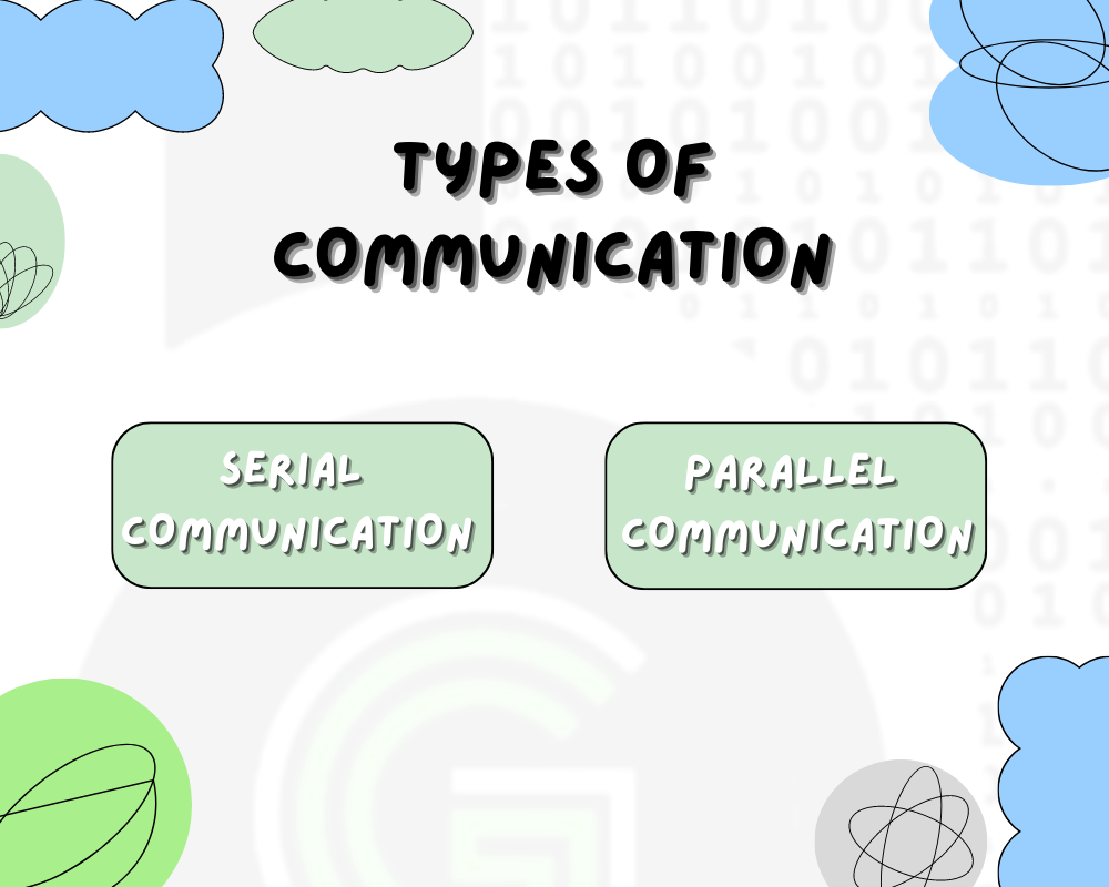
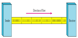
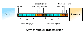
In Serial Communication the 8 bit data is transferred between 2 devices one bit at a time .This usually requires a single wire reducing the need for extra wires but compromising on the speed as the data is sent or received 1 bit at a time.This communication scheme is simple , cost effective and efficient for long distances and high frequencies.It also requires start and stop bits to synchronize the data.
In Parallel communication all the 8 bits are sent simultaneously along 8 input output lines.All the 8 bits are sent in a single cycle hence this data communication scheme is faster . This data transfer scheme is complex and efficient and faster at smaller distances. It needs no synchronizing bits as the data is received in a single clock cycle.
 UART IS A TYPE OF SERIAL DATA COMMUNICATION PROTOCOL

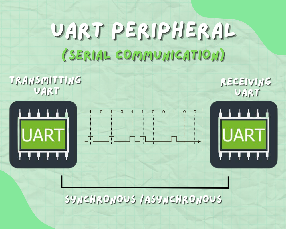
So UART is a type of serial communication protocol in which data is sent serially bit by bit over a single wire both in synchronous and asynchronous mode. In which each frame comprises of a start bit , a stop bit and 8 data bits with an exception of parity bits.
Types of communication in USART (serial) communication: –
DUPLEX- The data can be transmitted and received.
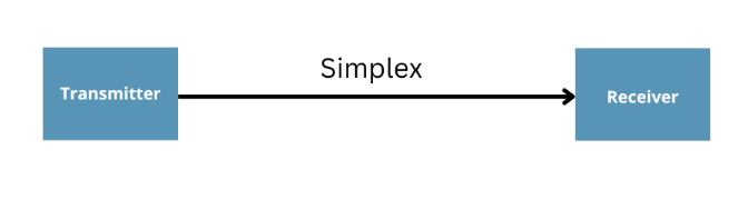
SIMPLEX- The data can only be transmitted or received.
Duplex can be further divided into: –
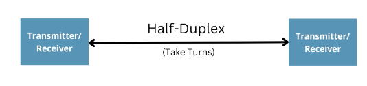
HALF DUPLEX-In this data can only be transmitted in only one way.
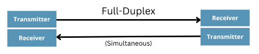
FULL DUPLEX- In this data can be transmitted both ways at a time.
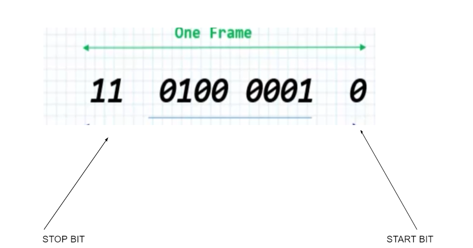
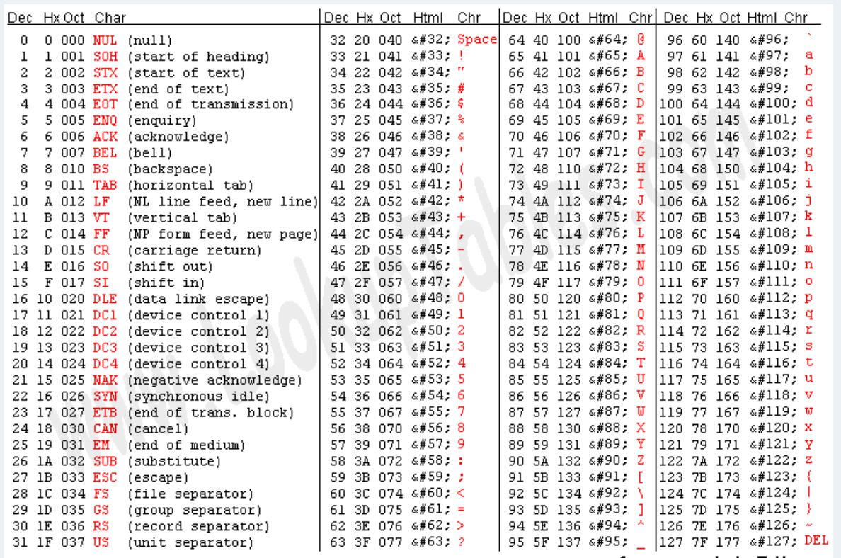
ASCII table is universal table, in which every English alphabet, mathematical number and different signs have been mapped to binary number in the hex and decimal format. Like in the below table, if u take character A, it is mapped to value of 0x41 which is in binary is: 01000001. That is what is transmitted as bits in word length in UART One Frame.
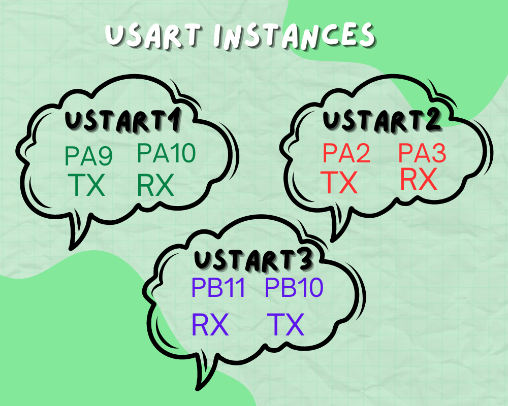
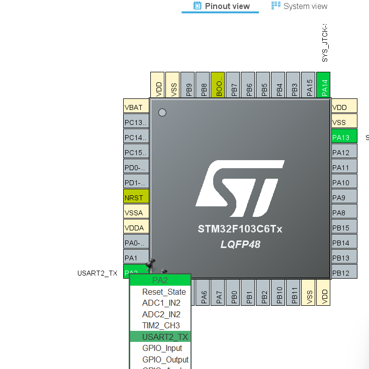
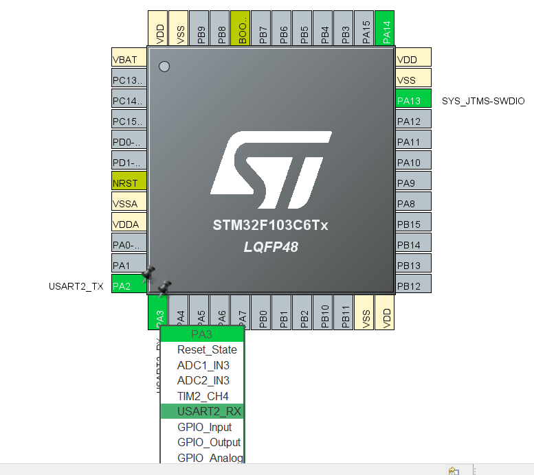
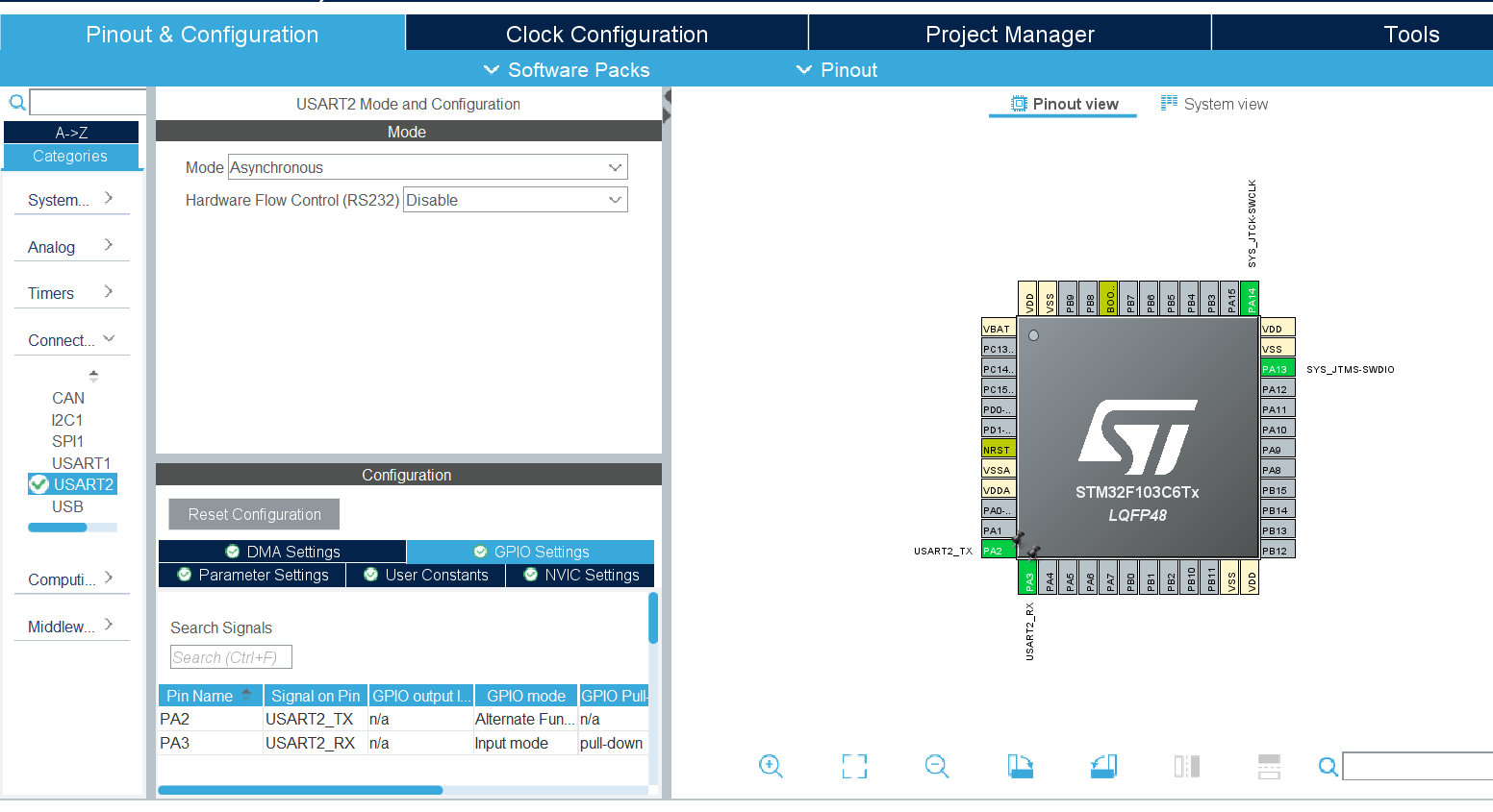
There are 3 usart instances USART1 , USART2 and USART3.
- To configure USART1 the pins the pin PA9 will be TX and pin PA10 will be RX
- In case of USART2 the pin PA2 will be TX and PA3 will be RX
- For USART 3 the RX and TX will be PB11 and PB10 respectively.
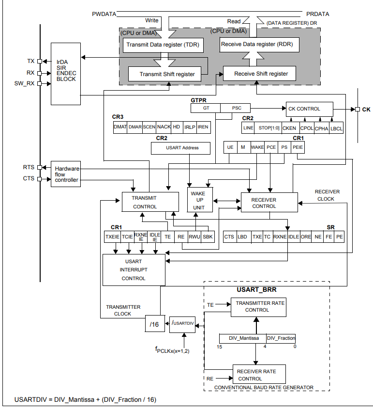
- The USART supports LIN (local interconnection network), Smartcard Protocol and IrDA (infrared data association) SIR ENDEC specifications, and modem operations (CTS/RTS).
- Smartcard is a single wire half duplex communication protocol.The smartcard mode can be selected by setting the SCEN bit in the USART_CR3 register while LINEN bit in the USART_CR2 register, HDSEL and IREN bits in the USART_CR3 register are kept in clear mode.The CLKEN bit may be set in order to provide a clock to the smartcard.
- The IrDA mode is selected by setting the IREN bit in the USART_CR3 register. In IrDA mode LINEN, STOP and CLKEN bits in the USART_CR2 register, SCEN and HDSEL bits in the USART_CR3 register are cleared.
- The LIN mode is selected by setting the LINEN bit in the USART_CR2 register. The STOP[1:0], CLKEN in the USART_CR2 register SCEN, HDSEL and IREN in the USART_CR3 register are cleared for the selection of LIN mode
USART MODE CONFIGURATIONS TABLE


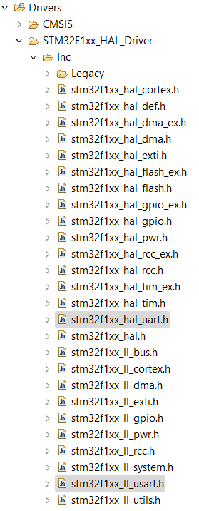
Stm32f1xx_hal_msp.c consists of void HAL_UART_MspInit which is used to initialize the gpio peripheral and configure hardware resources to act as UART module
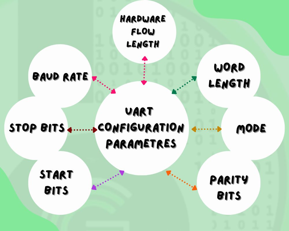
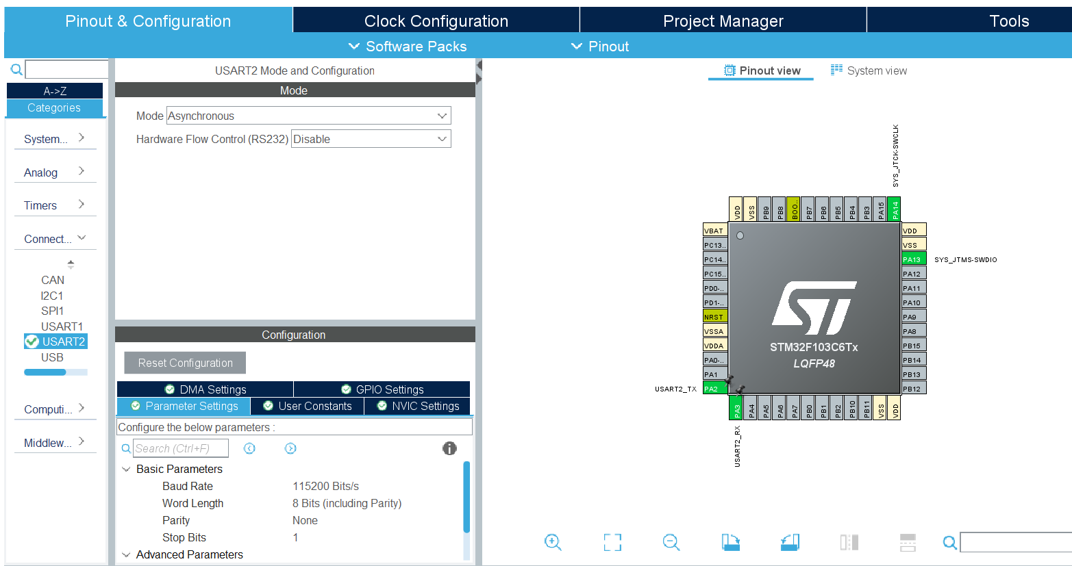
Stm32f1xx_hal_uart.h consists of UART init structure definition which consists of various parameters such as parity bits , stop bits,baud rate, word length, mode, Hwflowctl etc . It also consists of various macro definition , enum and error types.
Stm32f1xx_hal_uart.c consists of Uart macros , configuration and initialization of hardware resources configuring functions
- HAL_StatusTypeDef HAL_UART_Init (UART_HandleTypeDef * huart)
- HAL_StatusTypeDef HAL_UART_Transmit (UART_HandleTypeDef * huart, uint8_t * pData, uint16_t Size, uint32_t Timeout)
- HAL_StatusTypeDef HAL_UART_Receive (UART_HandleTypeDef * huart, uint8_t * pData, uint16_t Size, uint32_t Timeout )
- static void MX_USART2_UART_Init(void)
- void HAL_UART_MspInit(UART_HandleTypeDef* huart)
FUNCTION NAME
HAL_StatusTypeDef HAL_UART_Init (UART_HandleTypeDef * huart)
FUNCTION DESCRIPTION
Initializes the UART port according to the given parameters in UART_InitTypeDef and create the associated handle
PARAMETERS
UART_HandleTypeDef * huart – takes in pointer to the structure UART_HandleTypeDef that helps in configuring the port according to parameters specified by the UART module
RETURN TYPE
NONE
FUNCTION NAME
HAL_StatusTypeDef HAL_UART_Transmit (UART_HandleTypeDef * huart, uint8_t * pData, uint16_t Size, uint32_t Timeout) 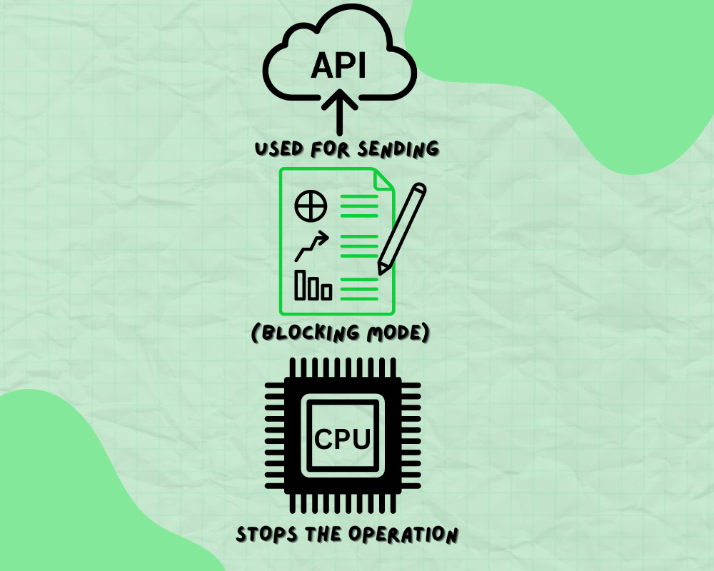
FUNCTION DESCRIPTION
This API is used for sending the data in blocking mode i.e the CPU stops the operation until the data is transferred
PARAMETERS
UART_HandleTypeDef * huart – The pointer to the structure UART_HandleTypeDef that contains the information of configuration of the uart module
uint8_t * pData – The pointer to the data buffer that stores the data
uint16_t Size – The size of the data to be sent(size of array or size of the string)
uint32_t Timeout – The time for which the blocking mode prevails
RETURN TYPE
HAL- STATUS
FUNCTION NAME
HAL_StatusTypeDef HAL_UART_Receive (UART_HandleTypeDef * huart, uint8_t * pData, uint16_t Size, uint32_t Timeout)
FUNCTION DESCRIPTION
Receives the specified amount of data in blocking mode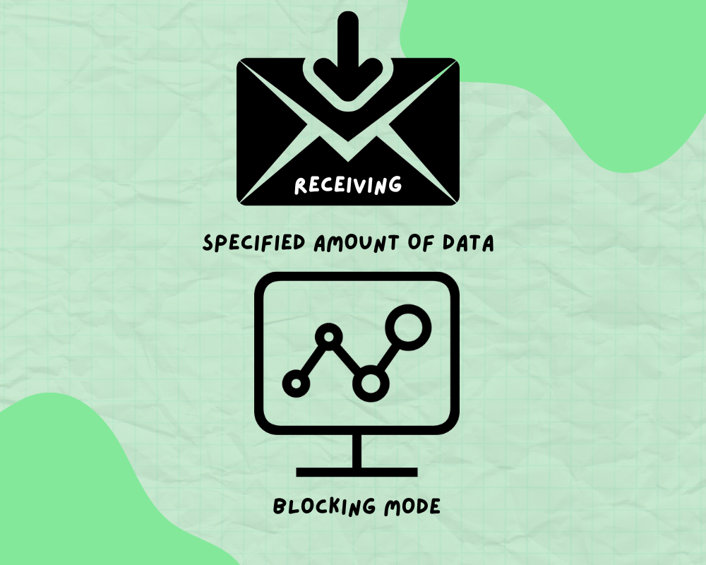
PARAMETERS
UART_HandleTypeDef * huart – The pointer to the structure UART_HandleTypeDef that contains the information of configuration of the uart module
uint8_t * pData – The pointer to the data buffer that stores the data
uint16_t Size – The size of the data to be sent(size of array or size of the string)
uint32_t Timeout – The time for which the blocking mode prevails
RETURN TYPE
HAL- STATUS
FUNCTION NAME
static void MX_USART2_UART_Init(void)
FUNCTION DESCRIPTION
Initializes the uart module according to parameters such as baudrate, wordlength, stopbits etc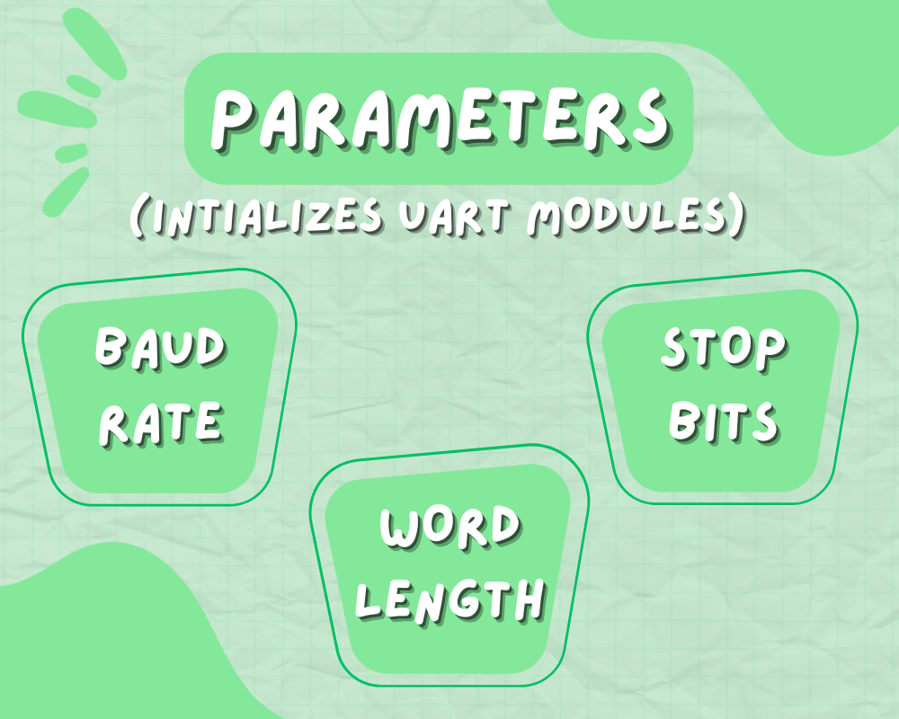
PARAMETERS
NONE
RETURN TYPE
NONE
FUNCTION NAME
void HAL_UART_MspInit(UART_HandleTypeDef* huart)
FUNCTION DESCRIPTION
Initialize the microcontroller support package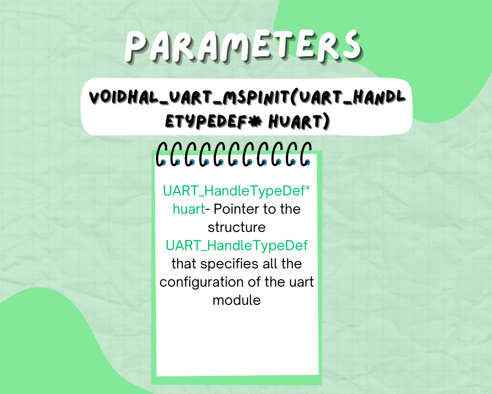
PARAMETERS
UART_HandleTypeDef* huart- Pointer to the structure UART_HandleTypeDef that specifies all the configuration of the uart module

Light Beige Sleek and Simple Blogger Personal Website by KsmaVideoEditor harsh gettobyte technp;pgies
Getting Hands-On with NXP eIQ: A “No Code” Starter Guide for Edge AI Developers
Introduction In a world driven by AI and IoT, deploying machine learning at the edge has become essential. NXP’s eIQ™

FRDM i.MX93 Demystified: The Hardware That Makes AI Work at the Edge
Imagine you’re handed a powerful little board, no bigger than your palm. At first glance, it looks like a jungle
How to Run AI on a Microcontroller or Microprocessor – A Beginner’s Guide to Edge AI
In the last few years, Edge AI has rapidly transformed how devices understand and interact with the world — without
Edge AI ToolKit: EiQ AI SDK
Introduction to EiQ In previous blogs, we’ve discussed in depth Edge AI, its features, advantages, and future scopes. Implementation of