
Get-To-Byte

Read and Write to a Rfid Tag

In the previous blogs we discussed how to read uid of different tags . Now as discussed in the applications of the rfid cards , the rfid tags can be used to store employee information so as to access certain restricted area. The rfid tags can also be used by retail stores to store customer information and points earned with each shopping. In this blog we’ll be learning how data reading or writing works by looking at the memory map of MIFARE 1K Tag and how to read and write the data using rc522.

UNDERSTANDING THE MEMORY MAP OF MIFARE 1K TAG

The memory of the MIFARE 1K Tag is divided into 15 sectors and each sector is divided into 4 blocks , within each block 16 bytes of data is stored 

Hence 16 Sectors * 4 Blocks * 16 Bytes=1024 Bytes = 1K 

The 0th Block of Sector 0 is used to store manufacturer data , this is usually 4 Byte UID(MIFARE 1K TAG, MIFARE Mini Tag) certain tags are available such as MIFARE Plus , MIFARE Desfire etc that has 7 Byte UID

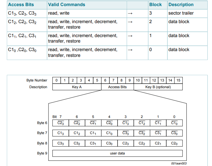
There are 3 data blocks presents in each sector and the last block in each sector is known as sector trailer.The 3 data blocks are used to store user data and the trailer block is used to deter mine the access conditions for all the blocks of the sector . The access conditions include Read , Write , Increment , Decrement ,Transfer and Restore.

Each sector trailer consists of following information:-

  • A mandatory 6 Byte Key A.

  • 4 Bytes for Access Bits.

  • Optional 6 Byte Key B (if not used, data can be stored).

FUNCTIONAL DESCRIPTION

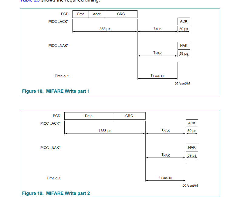
This function takes in 2 arguments the address to which the data has to be written and the array or buffer in which data  is stored lets say this to be writedata array.

A 8 bit  array of 18 length is also intialized to store data which will be transferred to the memory block.

Intially CRC is checked using CalculateCRC function using which takes in 3 arguments array in ( whose first 2 values are PICC Write and blockAddress ), len and output array that stores 2 values CRCResultRegL , CRCResultRegM .

Next MFRC522_ToCard function is called which takes in 5 arguments command (in this case that will be PCD_Transceive), send data , send length , back length, back data according to various commands processing is done and according to switch cases status is sent

Finally  MFRC522_ToCard in again called (with  PCD_Transceive) and the data is transferred to the FIFODataReg to return with the correct status and finally the PCD is set to idle
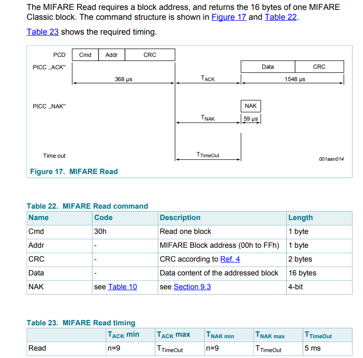
This function is used to read data from a memory block and and put it into a buffer or array hence the argument recvData

Similar to uint8_t MFRC522_Write initially the CRC is calculated and MFRC522_ToCard  is called.

In MFRC522_ToCard the command argument is set to PCD_TRANSCEIVE due to which the code enter the for loop in which the data that was in FIFODataReg is populated in the recvData Buffer.

Finally  MFRC522_ToCard in again called (with  PCD_Transceive) and the data is transferred to the FIFODataReg to return with the correct status and finally the PCD is set to idle
This function is used to control the MFRC522 according to the command arguments that can be

  • PCD_AUTHENT
  • PCD_TRANSCEIVE

Both these commands have different irqEn ,waitIRq that are written into CommIEnReg block which is then cleared using clear bit mask function 

After finally setting bit mask the PCD is set to idle state

The function writes the data in FIFODataReg to the backData buffer and returns the status which is OK in case of no errors
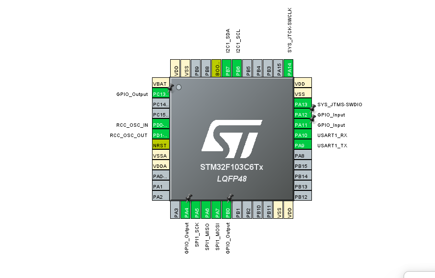
STM32CUBE IDE CONFIGURATION

FIG 1- PINOUT CONFIGURATION

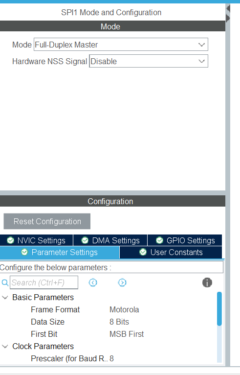
FIG 2 – CONFIGURING THE SPI1 PERIPHERAL

CODE

CODE EXPLAIN

We are declaring a buffer that is to be written in the desired memory block , the data that is to be written is also declared.

The buffer that will store the read data from the memory block after being written by MFRC522_Write function

In this step using the authorize function once the rfid tag is authorised the data is written to the desired memory block

In this block using the MFRC522_Write function the data is written to 24 memory block the data written is in the W array and is the second argument

In this step the data is read using MFRC522_Read function and is written back to the R buffer

Leave a Comment

Scroll to Top