


Primary Secondary Success Danger Warning Info Light Dark Link This page is Amazing
What is TRGMUX peripheral? TRGMUC provides an extremely flexible mechanism for connecting various trigger sources to multiple pins/peripherals. The trigger multiplexer (TRGMUX) module allows software to configure the trigger inputs for various peripherals. The TRGMUX module allows software to select the trigger source for peripherals. TRGMUX is a peripheral which provides mechanisms for connecting various trigger sources to multiple pins/peripherals. Each peripheral that accepts external triggers usually has one specific 32-bit trigger control register. Each control register supports upto 4 triggers and each trigger can be selected from available trigger sources.
What is Programmable Delay Block(PDB) peripheral? PDB provides controllable delays from either an internal or an external trigger, or a programmable interval tick, to the hardware trigger inputs of ADCs. PDB can also provide pulse outputs that are used as the sample window in the CMP block. The PDB contains a counter whose output is compared to several different digital values. If the PDB is enabled, then a trigger input event will reset the PDB counter and make it start to count. A trigger input event is defined as a rising edge being detected on a selected trigger input source, or if a software trigger is selected and the Software Trigger bit (SC[SWTRIG]) is written with 1
Add Your Heading Text Here
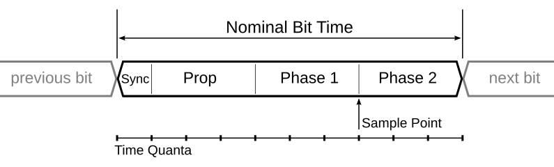
Bit timing in CAN is all about ensuring that every node on the network can correctly interpret the bits being transmitted. This synchronization is crucial for maintaining the integrity and efficiency of data communication. Bit Segmentation Each bit in a CAN frame is divided into several segments: Synchronization Segment (Sync_Seg): This is the part where the actual synchronization occurs. It’s always one-time quantum (TQ) long and helps align the clocks of all nodes on the network. Propagation Segment (Prop_Seg): This segment compensates for the physical delay in signal propagation across the network. Phase Segment 1 (Phase_Seg1): This is used to compensate for edge phase errors by lengthening the bit time if necessary. Phase Segment 2 (Phase_Seg2): Similar to Phase_Seg1, but it shortens the bit time if necessary. Each of these segments is made up of a certain number of time quanta (TQ), which are the smallest time units in a CAN network. Sample Point The sample point is a critical point within the bit where the bus level is read and interpreted as a logical value. Here’s why it’s so important: Accurate Bit Reading: The sample point is where the CAN controller reads the bit value. It is crucial to set the sample point accurately to minimize errors due to signal noise or other disturbances on the bus. Preferred Value: Typically set at 87.5% of the bit time, this value is preferred by protocols like CANopen and DeviceNet. This means that the bit is sampled after 87.5% of its duration has passed. Adjustable Range: The sample point can vary from 50% to 90% of the bit time, allowing flexibility depending on the network requirements and conditions. For example, ARINC 825 uses a default value of 75%. Noise Minimization: Setting the sample point correctly helps in minimizing the impact of signal noise. Sampling too early or too late can lead to incorrect bit interpretation, especially in noisy environments. Understanding Bit Rate and Bit Timing Bit Rate The bit rate in CAN communication refers to the speed at which data is transmitted over the CAN bus, typically measured in bits per second (bps). The bit rate is a crucial parameter because it determines how quickly data can be sent and received between nodes on the network. Common bit rates in CAN systems include 125 kbps, 250 kbps, and 500 kbps, with some systems operating at even higher speeds, such as 1 Mbps. Bit Timing Bit timing in CAN communication is the precise control of the duration and positioning of each bit transmitted on the bus. Proper bit timing ensures that all nodes on the network sample the bits at the same point, leading to accurate and synchronized data transmission. Bit timing is divided into several segments within each bit time, which collectively ensure robust and reliable communication. How Bit Timing Ensures Synchronization To maintain synchronization, the CAN controller can adjust the length of a bit by an integral number of time quanta (TQ). The maximum value of these adjustments is termed the Synchronization Jump Width (SJW). Hard Synchronization: Occurs on the recessive-to-dominant transition of the start bit. The bit time is restarted from this edge. Resynchronization: Occurs when a bit edge doesn’t occur within the Sync_Seg in a message. One of the Phase Segments is shortened or lengthened, depending on the phase error, up to the SJW. Factors Affecting Bit Rate Four primary factors influence the CAN bit rate: Oscillator Tolerance: Variations in the oscillator frequency can affect the timing accuracy. High-precision oscillators are essential for maintaining a stable bit rate. Propagation Delay: The physical length and quality of the CAN bus can introduce delays. Prop_Seg is adjusted to compensate for these delays. Network Load: Heavy network traffic can lead to delays and timing issues. Proper network design and bit timing configuration help mitigate these problems. Bus Length: Longer bus lengths introduce more propagation delay, requiring adjustments in the Prop_Seg to maintain synchronization. Prescaler Division The prescaler is used to divide the clock frequency to generate the required clock frequency for CAN. For example, if the clock frequency is 48 MHz and we need an 8MHz CAN clock, the prescaler value would be 6. How the Prescaler Division Works Clock Frequency: The original clock frequency provided by the oscillator. Prescaler Value: The value by which the original clock frequency is divided to achieve the desired CAN Clock Frequency. IMPORTANT The CAN system clock is chosen so that the desired CAN bus Nominal Bit Time (NBT) is an integer number of time quanta (CAN system clock periods) from 8 to 25. Time Quanta Definition: The time quantum (tQ) is the basic time unit in CAN bit timing. It is derived from the CAN system clock divided by the prescaler. Calculation: For example, if the CAN system clock is 48 MHz and the prescaler is set to 6, then: Nominal Bit Time (NBT) Definition: The Nominal Bit Time (NBT) is the total duration of a single CAN bit, measured in time quanta (tQ). It is the sum of the time segments within a bit period: Sync_Seg, Prop_Seg, Phase_Seg1, and Phase_Seg2. Components: Sync_Seg: The synchronization segment, always 1 tQ. Prop_Seg: The propagation delay segment, compensates for the signal propagation delay. Phase_Seg1: The first phase segment, can be adjusted to resynchronize the clock. Phase_Seg2: The second phase segment, also adjustable for resynchronization. Calculation: Practical Example of Bit Timing Calculation For calculating Bit Time and Segmentation, some important parameters are taken into account before starting the calculation. Parameters: Bit rate MCU Clock/Oscillator Frequency Bus length Bus propagation delay Propagation delay of TxD plus RxD offered by CAN Transceiver But, usually, values like total propagation delay offered by CAN transceiver, Bus length, and Bus propagation delay, are pre-defined values in their hardware datasheet. Question: Conclusion Understanding CAN bit timing and how the bit rate is adjusted is crucial for ensuring reliable communication in a CAN network. By properly configuring the timing parameters and taking into account factors like oscillator tolerance, propagation delay, network load, and bus length,
Table of Contents Why Was the CAN Protocol Introduced? Let’s start from the basics: why did we need the CAN protocol in the first place? Imagine the electronics in a car before CAN was introduced. Each part of the car’s electronics had to be directly wired to every other part it needed to communicate with. This point-to-point wiring system had some big problems: Too Many Wires: As cars got more advanced, they needed more electronic control units (ECUs) to handle all the new features. Each new feature meant adding more wires, making the system very complicated and heavy. High Costs: More wires didn’t just mean more complexity; it also meant higher costs. Building and maintaining such a complicated wiring system was expensive, and finding and fixing problems in all those wires took a lot of time and money. Hard to Expand: Want to add a new feature to the car? That meant even more wires and changes to the existing setup, which was a real headache. The system wasn’t built to easily handle new additions. Interference Problems: With so many wires, there was a lot of electromagnetic interference (EMI). This interference could mess up the signals being sent through the wires, making the whole system less reliable. Explaining the CAN Protocol The Controller Area Network (CAN) is a robust protocol for connecting electronic control units (ECUs) in vehicles and other distributed systems. CAN was introduced to address the need for a more efficient, reliable, and flexible communication system in automotive applications. Let us explore how CAN works, starting with its fundamental layers. The Physical Layer of CAN The physical layer of CAN consists of a two-wire bus system called CAN_H (high) and CAN_L (low). Data is transmitted differentially, meaning the voltage difference between the two wires represents the actual data. This approach provides excellent resistance to noise and interference, ensuring reliable communication among all nodes on the network. Data Link Layer in CAN The data link layer is responsible for managing the data exchange between nodes on the CAN network. It consists of several key functions: Framing: CAN frames consist of several fields, including the identifier, control, data, CRC, ACK, and end of frame. These fields structure the data and control information for transmission. Addressing: Instead of traditional addresses, CAN uses message identifiers for addressing. Each message has a unique identifier that determines its priority and relevance to nodes on the network. Error Detection: CAN employs multiple error detection mechanisms, such as the Cyclic Redundancy Check (CRC), acknowledgment checks, and form checks. If an error is detected, the erroneous message is discarded, and an error frame is transmitted. Arbitration: When multiple nodes attempt to send messages simultaneously, CAN uses a non-destructive bitwise arbitration process. The message with the highest priority (lowest identifier value) wins the arbitration and continues transmission, while others wait for the next opportunity. Importance of Synchronization Synchronization is critical for the correct operation of the CAN network. To achieve this, all nodes synchronize their clocks at the start of each message transmission and continuously resynchronize throughout the message. This synchronization ensures that all nodes interpret the bit timings accurately and maintain a consistent understanding of the message. Hard synchronization occurs at the beginning of every message. When a node receives the start bit, which is indicated by a transition from recessive to dominant, it aligns its clock with that transition. Resynchronization happens throughout the entire message. As the message is being sent, nodes continually adjust their clocks based on the expected bit timings. If a node detects that a bit transition occurred earlier or later than expected, it adjusts its internal clock to stay in sync with the others. Exploring the Versions of CAN Protocol The Controller Area Network (CAN) protocol has evolved over time, leading to various versions, each offering enhancements over its predecessors. Here, we’ll overview the different CAN versions, with a primary focus on CAN 2.0. Versions of the CAN Protocol 1. CAN 2.0A (Standard CAN) Identifier Length: 11 bits Message Size: Up to 2,048 unique message IDs Data Speed: Typically up to 1 Mbps Features: Standard data frames and error detection mechanism. 2. CAN 2.0B (Extended CAN) Identifier Length: 29 bits Message Size: Up to 536 million unique message IDs Data Speed: Typically up to 1 Mbps Features: Extended identifier field for more complex applications. 3. CAN FD (Flexible Data Rate) Enhanced Data Rate: Supports faster data transmission rates, up to 8 Mbps Data Length: Up to 64 bytes of data per frame Features: Flexible data rate and extended data field for more efficient communication. 4. CAN XL Higher Bandwidth: Supports even faster data rates, exceeding 10 Mbps. Extended Data Length: Capable of handling larger amounts of data Features: Improved protocol efficiency and higher performance for demanding applications Focus on CAN 2.0 While all versions of CAN offer unique advantages, our primary focus will be on CAN 2.0, the foundation of the CAN protocol. CAN 2.0A (Standard CAN) CAN 2.0A FRAME STRUCTURE OVERVIEW 1. Arbitration Field The Arbitration Field is crucial for determining the priority of the message during arbitration: SOF(Start of Frame); 1 bit Determines the starting Identifier: 11 bits Uniquely identifies the message. Lower values have higher priority. RTR (Remote Transmission Request): 1 bit Indicates if the frame is a data frame (0) or a remote frame (1) requesting data. 2. Control Field Reserved bit: 2 bits DLC (Data Length Code): 4 bits Specifies the number of data bytes (0 to 8) in the Data Field. This allows the receiver to know how many bytes to expect. 3. Data Field Data Field: 0 to 8 bytes Contains the message content. 4. CRC Field CRC (Cyclic Redundancy Check): 15 bits For error checking of the Data Field. CRC Delimiter: 1 bit (recessive). 5. Acknowledgment Field ACK Slot: 1 bit (dominant if the frame is received correctly). ACK Delimiter: 1 bit (recessive). 6. End of Frame End of Frame: 7 bits (recessive). 7. Interframe Space Interframe Space: Variable recessive bits. Interframe Space and

Dwell into this blog to know how to do CAN communication with automotive microcontroller. Start your journey to learn CAN communication protocol with simple DIY project using ElecronicsV3 board and CAN analyzer tool
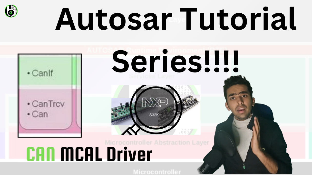
Autosar Layered Architecture
Add Your Heading Text Here Understand about protocol data unit in can Hardware Transmit Object