
In S32K144 MCU, UART can be used via 2 peripherals: LPUART & FlexIO.

LPUART is referred as Low Power Universal Asynchronous Receiver/Transmitter. LPUART is onchip peripheral only to do UART communication protocol. UART is a serial communication protocol which is done via UART peripheral in the Microcontrollers.
Also, in S32K144, there is FlexIO peripheral through which on-board serial communication protocols like UART, I2C & SPI can be emulated. So, through FlexIO peripheral, also UART peripheral can be implemented. To know about FlexIO peripheral in S32K144, refer to this blog.
Features of UART via LPUART peripheral in S32K144 MCU:
- LPUART peripheral of S32K144 supports full duplex mode and has NRZ data encoding (That is Logic 1 bit represents High value and Logic 0 bit represents Low value).
- It has programmable Baud rates(
- LPUART peripheral supports Interrupts mode, DMA mode or pooled operation mode for transmitting/receiving the data using LPUART protocol or for detecting below listed errors while LPUART communication session is happening:
- Transmit data register empty and transmission complete.
- Receive data register full.
- Receive overrun, parity error, framing error, and noise error.
- Idle receivers detect.
- Active edge on receive pin.
- Break detect supporting LIN.
- Receive data match.
- S32K144 also supports hardware parity generation and checking to ensure the integrity of the data while LPUART communication is happening.
- It has Programmable LPUART data length of 7-10 bits and LPUART stop bits of 1-2 bits.
- S32K144 MCU has feature to use the LPUART peripheral to wake up the MCU (if it is programmed in sleep modes), it can be waked up in either of the 3 below mentioned events:
- Idle line wakeup
- Address mark wakeup
- Receive data match.
- Support of request to send (RTS) and clear to send (CTS) signals, for hardware flow control, example of hardware flow control is a half-duplex radio modem to computer interface.
- Support of IrDA 1.4 format with programmable pulse width for IR communication.
- LPUART peripheral of S32K144 supports independent FIFO buffer for transmission and receiving of Data.
- Also, LPUART peripheral FIFO of S32K144 has additional features like:
- configurable watermark (lowest number of bytes) for transmit and receive buffer, when watermark is achieved corresponding status is changed of LPUART peripheral.
- Option for receiver to assert request after a configurable number of idle.
characters if receive FIFO is not empty.
Tx and Rx FIFO in S32K144 for all LPUART Instances both are of 4 words size. 1 Word is 1 byte(8 bits). So FiFo size is 4 byte long(32 bits).
LPUART Pinout and Hardware Instances
LPUART peripheral in S32K144 has 3 instances: LPUART0, LPUART1, LPUART2.
All the LPUART Instances has 4 pins:
- RX: Receiving of data
- TX: Transmission of data
- CTS: Clear to Send pin for hardware flow control.
- RTS: Request to Send for hardware flow control.

S32K144 UART Pins
Each LPUART instance supports all the 4 pins, with below mentioned pin details.
In LPUART0 there are following number of pins:
- For RX pin (LPUART Function) there are 3 MCU Pins.
- For TX (LPUART Function) there are 3 MCU pins
- For CTS (LPUART Function) there are 2 MCU pins
- For RTS (LPUART Function) there are 2 MCU pins.

In LPUART1 there are following number of pins:
- For RX pin (LPUART Function) there are 3 MCU Pins.
- For TX (LPUART Function) there are 3 MCU pins
- For CTS (LPUART Function) there are 3 MCU pins
- For RTS (LPUART Function) there are 3 MCU pins.

In LPUART2 there are following number of pins:
- For RX pin (LPUART Function) there are 3 MCU Pins.
- For TX (LPUART Function) there are 3 MCU pins
- For CTS (LPUART Function) there are 3 MCU pins
- For RTS (LPUART Function) there are 3 MCU pins.


LPUART SDK
S32K SDK/drivers provide an easy to use and quick way to use LPUART peripheral in S32K144, which is known as LPUART SDK.

Each S32 SDK driver can be configured and enabled to use in the project via S32 Configuration Tool. Will be digging into that part, in next section. For now, let’s understand the LPUART SDK in some detail, so as to use UART peripheral via LPUART.

In the SDK of LPUART there are header files and source files for LPUART Driver and LPUART Interrupt.
- LPUART interrupt files contains functions for using &configuring of LPUART interrupts and IRQ handler in S32K144 MCU.
- LPUART driver files contains functions for using/configuration of LPUART Peripheral.
LPUART Driver
LPUART driver files are further divided into LPUART Peripheral Abstraction Layer (PAL) & LPUART Low-level drivers., as shown below:

- LPUART Peripheral Abstraction Layer(PAL): contains functions and variables that are directly used in main.c or application code. And internally these functions use the LPUART Low-level drivers & LPUART IRQ . So if hardware is changed LPUART PAL would remain same and only internal low-level driver files need to be changed or modified. By this way we don’t have make many changes on application level.
- LPUART Low-level driver: contains functions that configures the LPUART peripheral registers for initializing the peripheral, using the peripheral and processing the data of peripheral at hardware level. These files are the ones which actually interacts with the hardware and make it configurable to our needs. 


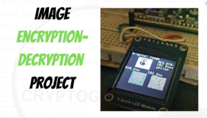
Secure Transmission of Image From one ECU node to another ECU node over CAN Protocol
https://youtu.be/kgsLO2cDsKI ST7789 LCD Screen Driver Stack with SPI MCAL Driver Contact Us Description: Embedded Software Driver for ST7789 LCD Screen

Cryptography Secure Boot Stack with Autosar MCAL Layer
GET IN TOUCH Contact us Got something on your mind? We’re all ears! Whether you have burning questions, awesome ideas,
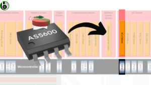
AS5600 Rotary Encoder Sensor Driver Stack with Autosar I2C Layer
GET IN TOUCH Contact us Got something on your mind? We’re all ears! Whether you have burning questions, awesome ideas,
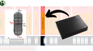
BNO055 IMU Sensor Driver Stack with Autosar I2C Layer
GET IN TOUCH Contact us Got something on your mind? We’re all ears! Whether you have burning questions, awesome ideas,
ESP8266 Wi-Fi Module Driver Stack with Autosar CDD Layer
GET IN TOUCH Contact us Got something on your mind? We’re all ears! Whether you have burning questions, awesome ideas,