

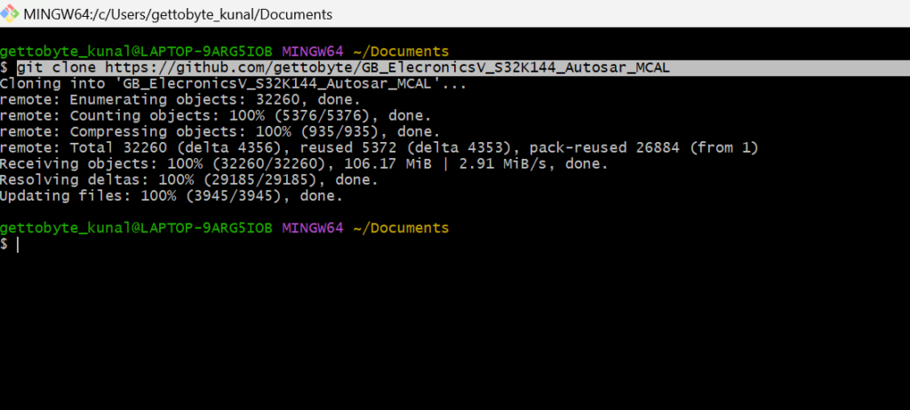
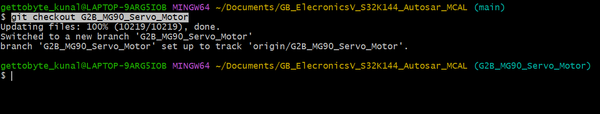
This is our central and main repo; we are developing number of functional demo codes via Autosar MCAL Driver’s, and we are committing them on different branches. One can see list of our branches:
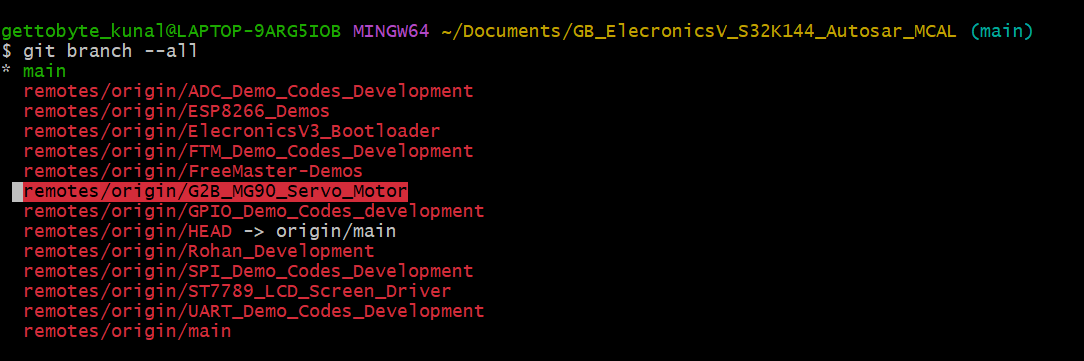
now switch to G2B_SG90_Servo_Motor Branch to get the SG90 servo motor Code with Autosar MCAL PWM Driver.
After that you can open the file explorer to see the Folder Contents of the Repo by start . command.

And now navigate to Sensor_Module Folder and their you will see SG90 Servo motor Demo code

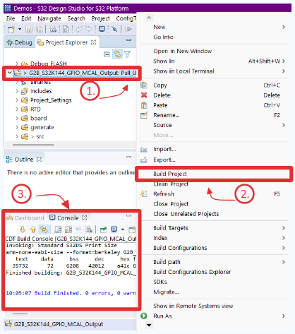
After that one can see the Example project in S32 DS. In which under Project Explorer view one can see all the folder’s of our Demo Project.

In Project Explorer, you can see all the files and folders of our Autosar MCAL Project. To give an high-level overview and understanding of all folders, refer ro below pic.
Out of all these folders, main folder’s of our concern would be: RTD, generate, S_M_Driver and src folder.
- RTD: has all RTD files (.c/.h) based on Autosar MCAL Compliant standard for configured peripherals.
- generate: has all generated configuration files according to Autosar MCAL Complaint Data Types, which stores information on how the configured peripherals have to be used.
- S_M_Drivers: Contain the external sensor_module library file, which is built on Autosar MCAL Driver API’s.
- Src: has our main application files. E.g example 1.c, example2.c and etc.
Autosar MCAL Driver Configuration for S32K144 Microcontroller’s is done via the .mex file. The .mex file is kind of like Code configuration file for NXP S32K1xx MCU’s, via which we can configure number of software stack’s and MCU components (like clock and pins) in GUI format. This .mex file also fully supports the Autosar MCAL Driver configuration. This gives us enablement to use and learn Autosar MCAL Driver’s menu section and configuration’s without the need of tools like EbTresos, DaVinci and ARXML files.
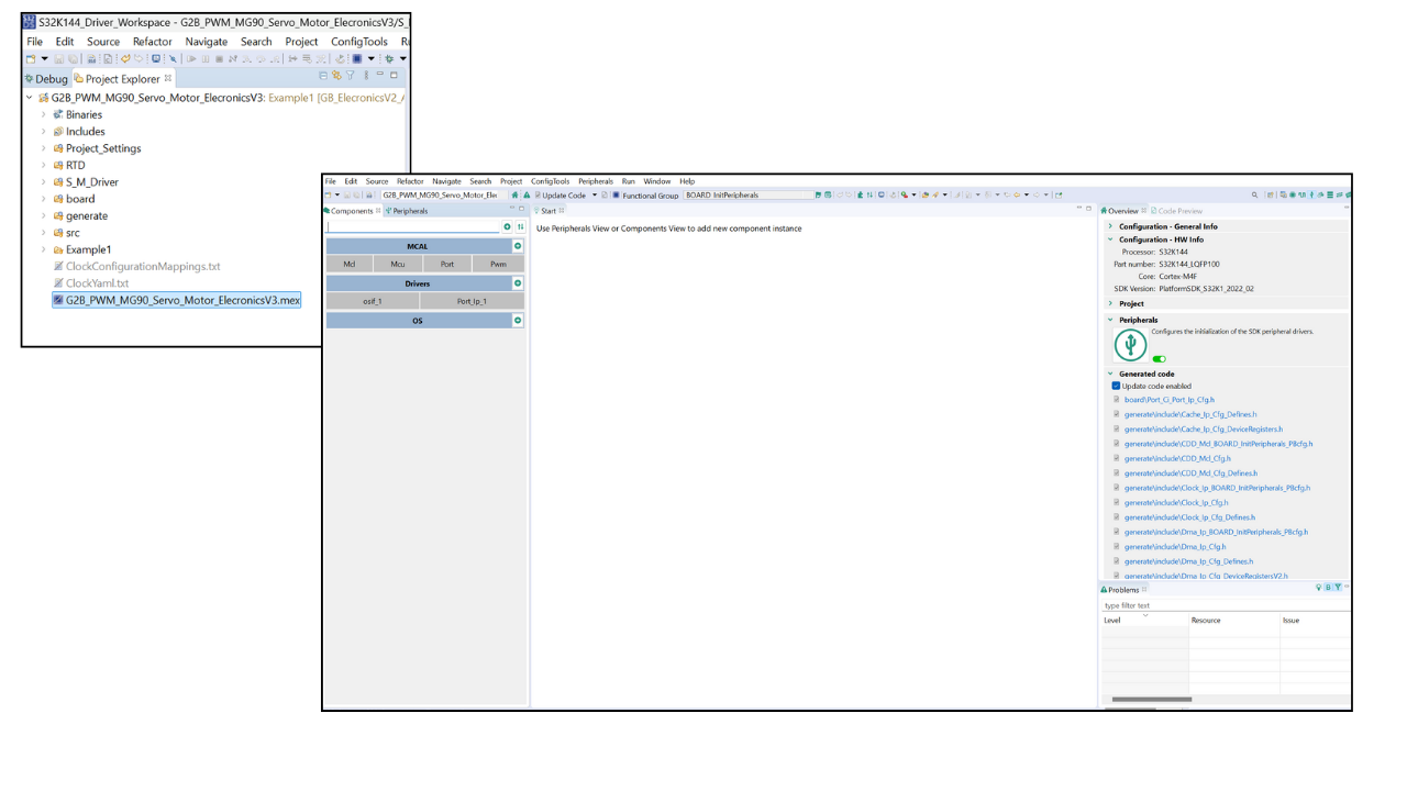
As our moto of these DIY projects and series is to understand the Autosar MCAL Driver’s, their configuration’s and how to use them so as to build skill set in Autosar Tech Stack. So NXP S32 Design Studio has integrated Autosar MCAL GUI for configuring NXP S32K MCU peripheral drivers. And this integrated GUI is accessed via .mex file of the project created in S32DS.

So, in our demo projects, though we are working with Autosar MCAL Driver but we are not going to use ARXML files, EBTresos and etc tools. As those tools are expensive, increases the overhead for learning core Autosar MCAL Driver concepts. And by using the .mex file based MCAL GUI, one can see changes in configuration code files as we make changes in GUI. Which makes thing relatively easy and hassle from learning point of view.
Now in our DIY Demo project series, we will not dwell into understanding of configuration of MCAL Driver’s, we will be focusing on usage of MCAL API’s, data types and chronology in which MCAL API’s has to be used for building automotive application’s.
For understanding the MCAL Driver concepts and configuration’s. refer to our Autosar MCAL Course: Autocal-V1.
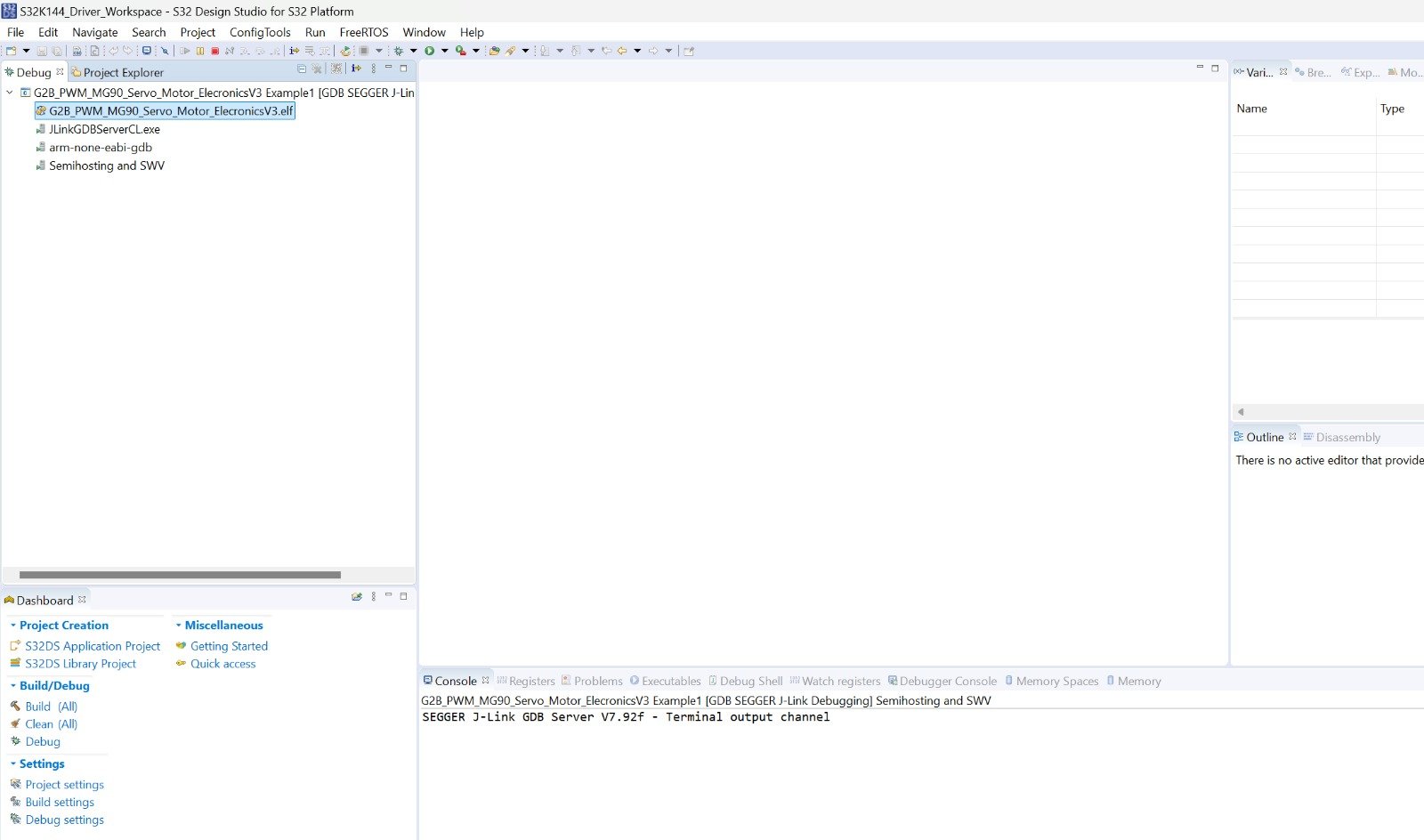
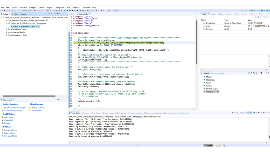
Now you are all set. just click that debug button and your code will be flashed into the S32K144 MCU and you’ll enter the debug mode where you can see example1.c source file and in that program is stopped at starting of main() function:

Demo Project Elf is not properly linked to S32 DS Debug Windows.
Step 1: Right Click on the project name under debug view.
Step 2: Terminate and Relaunch the Debug Session
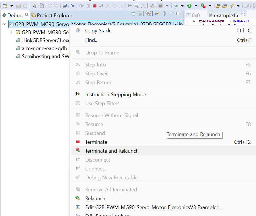
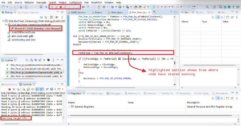
Step 3: Now project will be opened in Debug Mode successfully.
Step 4: If Problem Persists, erase the Firmware on the chip via Jlink Flash Lite Tool as told in Error 2. And then debug the project again.
Light Beige Sleek and Simple Blogger Personal Website by KsmaVideoEditor harsh gettobyte technp;pgies
Getting Hands-On with NXP eIQ: A “No Code” Starter Guide for Edge AI Developers
Introduction In a world driven by AI and IoT, deploying machine learning at the edge has become essential. NXP’s eIQ™
FRDM i.MX93 Demystified: The Hardware That Makes AI Work at the Edge
Imagine you’re handed a powerful little board, no bigger than your palm. At first glance, it looks like a jungle
How to Run AI on a Microcontroller or Microprocessor – A Beginner’s Guide to Edge AI
In the last few years, Edge AI has rapidly transformed how devices understand and interact with the world — without
Edge AI ToolKit: EiQ AI SDK
Introduction to EiQ In previous blogs, we’ve discussed in depth Edge AI, its features, advantages, and future scopes. Implementation of