Embedded Basics Miscellaneous

Table of Contents

Communication Protocols in Embedded System

  • Serial communication

In serial communication, we have only one line for transmitting and receiving data which is why it is half-duplex. It is best for high frequencies as it uses only a single bus or channel for communication, but it can be a bit slower than parallel as it sends only a single bit per clock pulse also because of the single wire here we have fewer chances of cross-talks. It can detect the error as well.

When transferring a bit quick change in voltage are required like for 5v OS, 0 bit communicated as a short pulse is 0v, and 1 bit communicated by a short pulse of 5v. In serial communication, the first bit is the most significant bit and the last one is the least significant bit.

  • Parallel Communication

In parallel communication, we have a number of lines or buses equal to the number of bits we are transferring. We call it full duplex as the line for transmitting and receiving bits is different. It is faster for small frequencies as all bits are sent at once but as we have to use multiple wires it is costlier also here, we have lots of chances of cross-talks.

As in serial, here also we have the first bit is the most significant bit and the last one is the least significant bit.

How do they convert?

The protocols we have read above communicate in serial form, but they get the data from their peripheral device in parallel form. How do bits get converted into serial form to parallel form? Suppose we have 4 bits, to convert them from parallel to serial we need a Parallel to Serial converter, In the same way, if we want to convert parallel from series, we need a serial to parallel converter. Here comes the D Flip-Flop which is specially designed for such conversions.

What is Flip-Flop?

A basic memory element or basic digital memory circuit is known as Flip-Flop. It is some medium in which one bit of information (1 or 0) can be stored or retained until it\’s necessary.

  • As one flip-flop can store one bit of information. To store multiple bits, we need multiple flip-flops.
  • The group of flip-flops, which are used to store the binary data is known as register.

Flip flop circuits are classified into four types based on their use:

  1. D-Flip Flop
  2. T- Flip Flop
  3. SR- Flip Flop
  4. JK- Flip Flop.

Here for conversion between Serial and parallel bits of data D-Flip Flop is used.

Now, what is D Flip-Flop?

D flip-flop is also known as Data or Delay Flip-Flop. It has a single D input and a clock input C which is why we call it a D flip-flop. Or for the word delay, it describes what happens to the data at input 0. The data at D input is delayed by one clock pulse before it gets to the output Q.

There are two different ways of conversions:

  1. Parallel to Serial conversion.
    • First, we need Flip-Flops equivalent to the number of bits. Then we will put the multiplexer in between the Flip-Flop.

    Multiplexer- It is a combinational circuit that takes input from one of many input lines(parallel) and directs it to a single output line(serial).

    It has two inputs:

    1) From the previous Flip-Flop

    2) From Parallel bit data.

    Now we will load the data which will be transferred one by one.Here msb will be transferred first.

  2. Serial to Parallel conversion.
  • First, we need Flip-Flops equivalent to the number of bits. This time we won\’t put the multiplexer in between the Flip-Flop.
  • We need to store all the bits at first for this we will pull the clock signal low. Once all bits are loaded, we will pull the clock signal high, and it will shift the LSB to the input of Flip-Flop 1 and output of Flip-Flop 0. Same way all bits gets transferred.
  • Now all the bits are stored in these Flip-Flop and as shown above all the Flip-Flop will transfer the bits at once the way it happens in parallel..

Overview about Serial Communication Protocols in MCU

UART Protocol

  • What is UART Protocol?

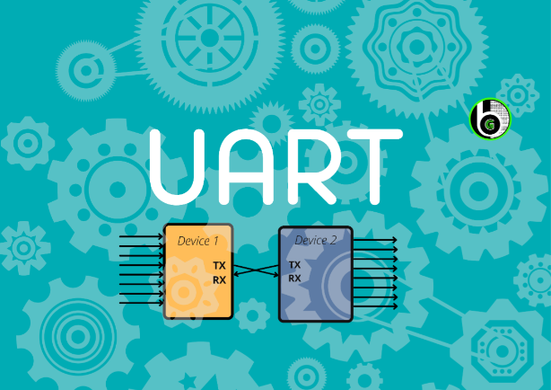
UART stands for Universal Asynchronous Receiver/Transmitter. As we can understand by the name it says it receives and transmits asynchronously. Asynchronously means it doesn\’t use clock pulse to synchronize the transmitter and the receiver.

In UART, the transmitter takes the signals in parallel from a controlling device[ex-CPU] then it sends the bits to a receiver in serial then the receiver converts those bits in parallel again. UART follows one master one slave approach as it uses only 2 wires for communication. It has one transmitter and one receiver.

  • How does it work?

As I, ve mentioned above it transmits asynchronously hence it uses a start and stops a bit, in it contains main data and a parity bit. The parity bit is only needed if the device needs to check the error.

When the device wants to start the communication, it pulls the transmitting line low which means it sends a 0 bit and receiving device understands that the transmitter wants to send the data. When the transmission line goes lows it stays low for one clock pulse and then it starts sending the data of 8 bits then the 9th one is a parity bit, the last one is stopping bit it stays high for the one clock pulse until the transmitter sends a low bit to start another frame.

To get, in detail understanding on UART Protocol, refer to this blog.
UART Protocol in Embedded System

SPI Protocol

  • What SPI Protocol is?

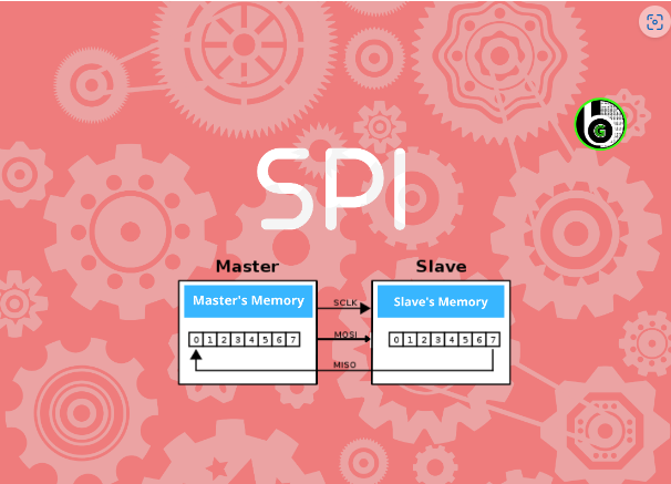
SPI stands for Serial Peripheral Interface. Just like UART it also uses Serial Communication for transmitting and receiving data but instead of asynchronous it uses synchronous communication protocol for transmission. 

Synchronous means the transmitter and the receiver must have the same clock signal. It uses a Full duplex communication protocol which means it can send and receive at the same time. SPI follows one Master multiple slave configuration.

  • This protocol has 4 parts

1. MOSI-Master Out Slave In

Here Master sends data to the slave and the slave receives the data. Master sends data to each device it is connected to via a single wire.

2. MISO-Master In slave out

Here Slave sends the data to the master and the master receives the Data. Master receives the data from each device it is connected to through a single wire.

3. CLK-Clock Signal

It is important for synchronizing the data when the master sends or receives it.

4. CS/SS-Chip select/slave select

We have different wires connected to the chips. Suppose we have 3 chips connected. Then the master would have three wires cs1,cs2,cs3 connected from chip1, chip2,chip3 individually.

To get in detail understanding on SPI Protocol, refer this blog.
SPI Communication in Embedded

I2C Protocol

I2C stands for the inter-integrated circuit. If you have read carefully about SPI and UART you will find I2C got the best features of these two.

It follows multi-master protocol as multiple masters through a single slave or to multiple slaves. It is a half-duplex communication protocol since it has only one line for transferring and receiving data. It is also called Two Wired Interface as it uses two wires for communication.

  • This protocol has 2 parts
  1. SDA: For sending bits
  2. SCL: For synchronizing the data.
  • How does it work?

In I2C as we have multiple slaves, every slave must have a different address before sending a bit master will address or call the receiver. If we have multiple masters then the master will check the clock signal. If it is high it will send the data or if it is low then it means another master is sending the data at the moment.

To get more in detail understanding of I2C protocol, refer to this blog.


Conclusion Para

  1.  In the end, if you want to use two devices then UART works best and fastest.
  2. If you have multiple slaves and one master then I would suggest going for SPI 
  3. And if you want to connect one slave with multiple masters then I2C is the fastest as it lowers the wirings as well.

Other blogs to explore

About Microcontrollers

Current/Power Sensors
Kunal Gupta

Allegro\’s AC Power monitoring IC ACS71020

In many applications, we want to monitor AC electrical parameters like Solar chargers, motor control, Battery Charging stations, or Smart energy meters. Measurement of AC current and voltage, by the means of the electronics, is a quite tricky part, unlike traditional electromechanical systems. Below is a basic block diagram to know about it. AC voltage and current signals are first steps down to low voltage and current values.One can not feed High AC electrical voltage and Current signals which can range from 0-1000 units and are even larger than that, in some applications(Power systems, AC motors and etc)  to the electronics and digital world.  So at first by the use of one of the below listed three methods AC signals are brought to low values( 0-10V, 0-5A) Use of Current Transformer,  Potential Transformer, or  Rogowski coil. Use of shunt resistors. Use of Hall effect-based principal for current measurement.  The signals which we get after processing from these methods are fed into the Digital System where there are signal conditioning circuits, data acquisition circuits, digital signal processing by the use of Digital and Analog Electronics. The Digital System part is designed to embedded into the Integrated chips(ASIC) which are specially designed with the purpose of Energy Metering application. For the digital computation of key electrical parameters like Power factor, Active power, reactive power, Vrms, Irms and etc. Using these key parameters we can monitor the AC electrical parameters through serial interfaces like SPI/I2C with Host MCU. ACS71020 Energy Metering IC Allegro microsystem\’ AC power monitor module ACS71020 is a Single-phase energy monitoring IC that works on the principle of the HALL effect sensing technique (To know about ways to measure current refer to this blog) to measure the AC current and resistor divider network to measure the input AC voltage. It calculates the key electrical parameters using its  Metrology Engine and digital system from which it sends the data to the host MCU via I2C and SPI interfaces. The Voltage and current reading that we get from AC voltage and Current measurement blocks via the sense amplifiers are analog in nature. The analog signals from respective Voltage and Current blocks are then fed into the internal ADC\’s(Analog to Digital converter). ADC samples the current and voltage channels at high frequency and then digitally converts them by filtering and decimating the output signal from sense amplifiers to avoid large anti-aliasing filters. The digital word from the ADC is 16 bits for both the current and voltage, which is fed to the digital system for further calculation of other electrical parameters. Its Key Features are: Without the need for any Transformer, Rogowski coils, oversized current transformers, or the power loss of shunt resistors one can calculate Vrms and Irms up to 517V and 90A respectively It has an advanced digital system with galvanically isolated current sensing technology which achieves reinforced isolation ratings in a small PCB footprint Apart from the calculation of Electrical Key parameters it also has many extra features too which are essential for monitoring purposes. ACS71020 IC Pinout Diagram and Pins description ACS71020 IC has 16 pins, Starting from Pin 1-8 are current channel pins, out of which pins 1-4(Fused internally) are all IP+ and pins 5-8(fused internally) are all IP-.  Pins 16-15 are Voltage measurement pins  ACS71020 IC Schematic For using ACS71020 for typical applications its schematic is pretty easy and less complicated in oppose to other metering IC\’s(STMP32 & ADE series). ACS71020 can be powered directly from the same supply as the system\’s MCU, through its reinforced isolation technology it does need multiple power supplies to power it up. So Vcc and GND pins are connected directly to MCU Vcc and GND pins. I2C  pins are at a high level(5V or 3v3), before the start of the I2C Serial Communication, thus SDA and SCL lines are connected with a pull-up resistor. When using in I2C mode, pins 9 & 10 act as DIO_1 and DIO_0( Digital Input/Output)  respectively, which are connected directly to MCU Digital Pins( Will get in detail about DIO pins in a later section) For SPI communication, MOSI, MISO, CE pin are at a high level and CLK is at GRND before the start of SPI serial Communication. When using in SPI mode, pins 9 &10 are used as MOSI and CS pins. ACS71020 IC  measures the Current and voltage of the input AC signal to calculate all other key parameters. So for inputting the AC voltage & current signals to the ACS71020 IC we will focus on Voltage channel pins(VINP & VINN) and Current channel pins(IP+ & IP-). One thing to recall is that in a single-phase AC supply there are two terminals: Live Wire (Black/Red) carries electricity from the power supply and takes it to the load. Neutral wire(Blue wire) returns the electricity from the load to the power supply to make the circuit complete. VINN &VINP are terminals from where AC voltage is measured, so resistor network divider of 1mega ohm and shunt resistor is made in b/w the VINP and VINN terminals to fit the input AC voltage within the Range of the differential voltage input buffer of ACS71020( +-275mv) as specified in electrical characteristics of the datasheet. IP+[1:4] & IP-[5-8] pins are terminals for AC current measurement. IP+ terminals are fused internally and are connected to a neutral wire of load and IP- terminals are also fused internally and are connected to a neutral wire of supply to complete the current loop of the current channel. EVE ACS71020 Module For doing the practical demonstration with ACS71020 IC we are going to use the EVE ACS71020 breakout board, which is manufactured by the Evelta. The module is cheap and can be used easily with HOST MCU via I2C or SPI communication. The module has pull-up resistors of 10k ohm placed with SDA and SCL pins( pins 12 & 11) of ACS71020  and no pull-up resistors are connected with MOSI and CS  pins(pins 10 & 9) means we can use these

Read More »

Introduction to STM32WB55

Table of Contents About STMicroelectronics STMicroelectronics is a leading provider of semiconductor solutions that are seamlessly integrated into billions of electronic devices used by people worldwide on a daily basis. The semiconductor company builds products, solutions, and ecosystems that enable smarter mobility, more efficient power and energy management, and the wide-scale deployment of the Internet of Things and connectivity technologies. To know more about STMicroelectronics refer to its website: www.st.com. Going back in history, ST was formed in 1987 by the merger of two government-owned semiconductor companies: Italian SGS Microelettronica (where SGS stands for Società Generale Semiconduttori, “Semiconductors’ General Company”), and French Thomson Semiconductors, the semiconductor arm of Thomson. In this blog, we are going to start with ST IoT-based Nucleo Board STm32WB55. What is STM32WB Series all about? The STM32WB55xx and STM32WB35xx are advanced multiprotocol wireless devices that boast ultra-low-power consumption. These devices are equipped with a powerful and efficient radio that is compliant with the Bluetooth® Low Energy SIG specification 5 and IEEE 802.15.4-2011 (Zigbee). Additionally, they feature a dedicated Arm® Cortex®-M0+ processor that handles all real-time low-layer operations. These cutting-edge devices are perfect for a wide range of applications that require reliable and efficient wireless communication. Whether you’re working on a smart home project, a wearable device, or an industrial automation system, the STM32WB55xx and STM32WB35xx are the ideal choices. With their advanced features and capabilities, these devices are sure to revolutionize the way we think about wireless communication. So why wait? Start exploring the possibilities today and discover what the STM32WB55xx and STM32WB35xx can do for you! The devices have been meticulously crafted to operate on minimal power and are built around the high-performance Arm® Cortex®-M4 32-bit RISC core, which can operate at a frequency of up to 64 MHz. This core boasts a Floating-point unit (FPU) single precision that supports all Arm® single-precision data-processing instructions and data types. Additionally, it is equipped with a full set of DSP instructions and a memory protection unit (MPU) that enhances application security. These devices have been designed with the utmost care and attention to detail, ensuring that they are not only efficient but also highly effective. The Arm® Cortex®-M4 32-bit RISC core is a powerful tool that enables these devices to perform at an exceptional level, while the FPU single precision and DSP instructions provide unparalleled accuracy and precision. Furthermore, the memory protection unit (MPU) ensures that your applications are secure and protected from any potential threats. Enhanced inter-processor communication is provided by the IPCC with six bidirectional channels. The HSEM provides hardware semaphores used to share common resources between the two processors. The devices embed high-speed memories (up to 1 Mbyte of flash memory for STM32WB55xx, up to 512 Kbytes for STM32WB35xx, up to 256 Kbytes of SRAM for STM32WB55xx, 96 Kbytes for STM32WB35xx), a Quad-SPI flash memory interface (available on all packages) and an extensive range of enhanced I/Os and peripherals.  About STM32WB55 Architecture Memories Security and Safety True random number generator (RNG) RF Subsystem Low Power Modes Clocks and Startup General Purpose Input Output(GPIOs) Direct Memory Access (DMA) Interrupts and Events Analog to Digital Convertor (ADC) Comparators (COMP) Touch Sensing Controller Liquid crystal display controller (LCD) Timers and watchdogs Real-time clock (RTC) and backup registers Inter Integrated Circuit (I2C) Universal Synchronous/Asynchronous Receiver Transmitter (USART) Serial Peripheral Interface(SPI) Serial audio interfaces (SAI) Quad-SPI memory interface (QUADSPI) Architecture Architecture STM32WB55 Architecture The host application is housed on an Arm® Cortex®-M4 CPU (named CPU1) that connects with a generic microcontroller subsystem. The RF subsystem is made up of a specialized Arm® Cortex®-M0+ microprocessor (named CPU2), Bluetooth Low Energy and 802.15.4 digital MAC blocks, an RF analog front end, and proprietary peripherals. All Bluetooth Low Energy and 802.15.4 low-layer stack functions are handled by the RF subsystem, which limits communication with the CPU1 to high-level exchanges. Some functions are shared between the RF subsystem CPU (CPU2) and the Host CPU (CPU1): Flash memories  SRAM1, SRAM2a, and SRAM2b (SRAM2a can be retained in Standby mode)  Security peripherals (RNG, AES1, PKA)  Clock RCC Power control (PWR) Memories Memories STM32WB55 Memories 2.1.  Adaptive real-time memory accelerator (ART Accelerator) The ART Accelerator is a memory accelerator optimized for STM32 industry-standard Arm® Cortex®-M4 processors. It balances the inherent performance advantage of the Arm® Cortex®-M4 over flash memory technologies. To release the processor near 80 DMIPS performance at 64 MHz, the accelerator implements an instruction prefetch queue and branch cache, which increases program execution speed from the 64-bit flash memory. Based on CoreMark benchmark, the performance achieved thanks to the ART accelerator is equivalent to 0 wait state program execution from flash memory at a CPU frequency up to 64 MHz. 2.2.  Memory protection unit In order to prevent one task from unintentionally corrupting the memory or resources used by any other active task, the memory protection unit (MPU) is used to manage the CPU1’s accesses to memory. This memory area is organized into up to eight protected areas. The MPU is especially helpful for applications where some critical or certified code must be protected against the misbehavior of other tasks. It is usually managed by an RTOS (real-time operating system). 2.3.  Embedded flash memory The STM32WB55xx and STM32WB35xx devices feature, respectively, up to 1 Mbyte and 512 Kbytes of embedded flash memory available for storing programs and data, as well as some customer keys. 2.4.  Embedded SRAM The STM32WB55xx devices feature up to 256 Kbytes of embedded SRAM, split in three blocks: SRAM1: up to 192 Kbytes mapped at address 0x2000 0000  SRAM2a: 32 Kbytes located at address 0x2003 0000 also mirrored at 0x1000 0000, with hardware parity check (this SRAM can be retained in Standby mode)  SRAM2b: 32 Kbytes located at address 0x2003 8000 (contiguous with SRAM2a) and mirrored at 0x1000 8000 with hardware parity check. Security and Safety Security and Safety The STM32WB55xx  contain many security blocks both for the Bluetooth Low Energy or IEEE 802.15.4 and the Host application. It includes:  Customer storage of the Bluetooth Low Energy and

Read More »

Debugging Technology in Microcontrollers

Want to know how to debug the microcontrollers? Want to know how to use debugging tools like step-in, step-out, breakpoints and etc. If yes then you have to right place. Explore this blog to understand about Debugging technology in microcontroller’s with NXP S32K144 MCU using ElecronicsV2 board

Read More »
Kunal Gupta
Author: Kunal Gupta

Author

Kunal Gupta

Leave a comment

Stay Updated With Us

Error: Contact form not found.

      Blog