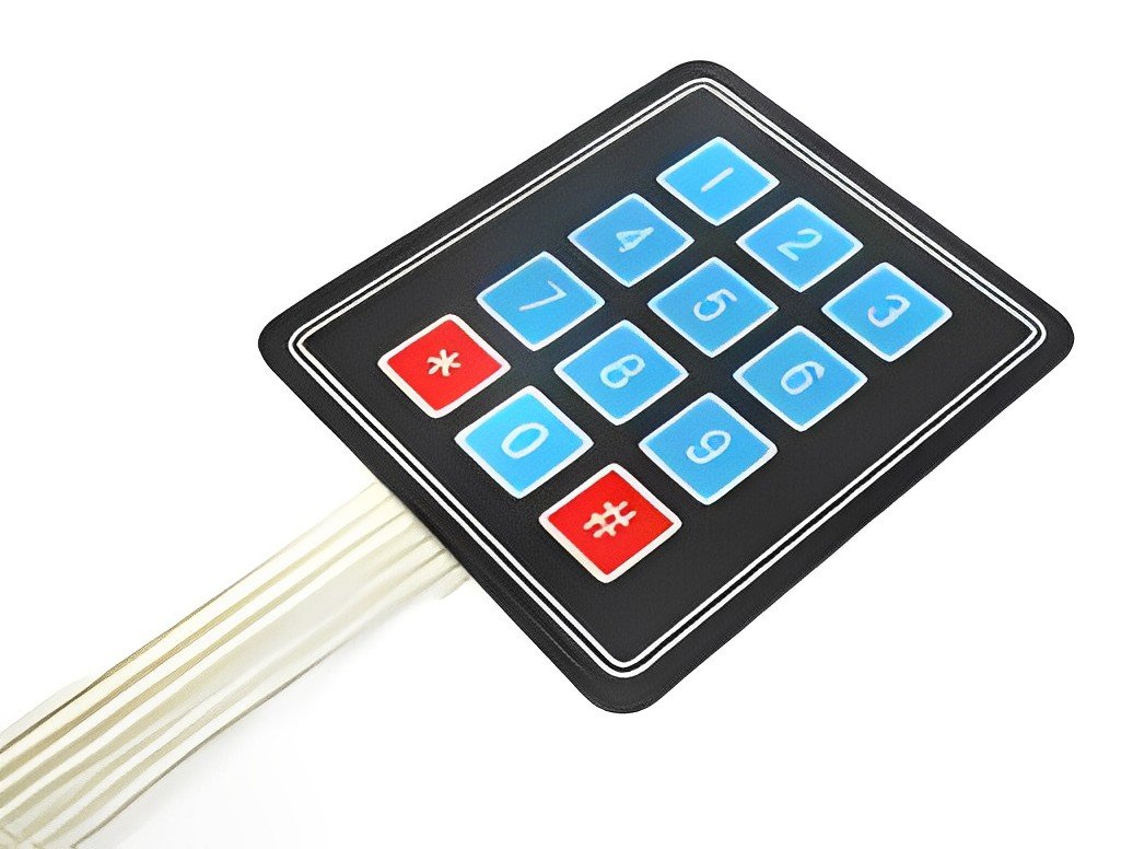
Over 10 years we help companies reach their financial and branding goals. Engitech is a values-driven technology agency dedicated.

Gallery

Contacts

411 University St, Seattle, USA

engitech@oceanthemes.net

+1 -800-456-478-23

Sensor/Module Interfacing Sensors and Modules Tech

Keypad Module in Embedded

Table of Contents

What are Keypad Modules ?

Keypads are input devices that most of us are familiar with  that help us communicate with a machine , by pressing a set of buttons or keys and giving it a set of instructions to perform tasks.We see them at ATMs, Phones,,military, even Refrigerators , Vending Machines etc constantly evolving and changing over the years such as membrane keypads,dome-switch keypads, capacitive touch keypads etc. Keypad modules are basically sets of buttons , keys or switches arranged in  rows and  columns in matrix form which establishes a connection when a button is pressed and this information is transmitted to the machine.Keypads play an important role in human machine communication be it an operator in a factory or a child buying a beverage from a vending machine . But all these variety of applications of the keypads showcases the different types of keypads and the technologies they employ.

Types of Keypad Modules

Membrane type keypad modules are most commonly used in commercial applications as well as household appliances such as refrigerators , coolers, calculators etc. They are  made of 3 layers :

When the user presses a key the stainless steel button and the bottom layer comes in contact completing the circuitry which is then sent to the external ribbon as a signal . The size of these  layers are as thin as membrane hence the name membrane. Each of the layer is a half of the circuit that is connected to the external ribbon which acts as a communication path between human machine interface.

The PCB type keypad module consists of a PCB which is designed in such a manner that connections are made between each row and column on which mechanical push buttons are soldered . The connections between rows and columns are then finally ended on the 8 connector pins which are connected to the machine to identify the location of the button pressed.These can be customized as per the need. They are widely used in the phones and cheaper , easy to install and have a relatively long life.

The capacitive touch type keypad module as the name implies uses the change in capacitance upon application of the touch as a measure to detect the human interface  . The human finger acts as a dielectric which increases the capacitance . This increased capacitance causes an increase in the charging and discharging time which is monitored and classified as touch. These are often used over their counterparts such as resistive type which are slower and less smoother.Since change in capacitance is involved these modules are also sensitive high levels of heat , light , temperature changes, liquid application  etc. To counter the behavior  of touch keypad modules under the exposure to the liquid the texas instruments keypad module uses mutual capacitance rather than self capacitance to classify a touch and distinguish false touches.

It’s a combination of a flat-panel membrane and mechanical-switch keypad. They feature two circuit board traces embedded under a silicone keypad with a dome-shaped switch. These domes create tactile feedback when pressed, making them particularly useful in commercial and work-related applications. Furthermore, dome-switch keypads have a high level of reliability, often lasting for as many as 5 million cycles.

In this keypad module the keys are designed like scissors. They also have a rubber dome key such as in dome switch but they have improved functionality  by keeping the keys connected together . They may have better functionality but they tend to be expensive and are high maintenance. They are different Scissor Switch type in the market but in general they have 3 layers.

4 x 3

The 4x3 keypad module as the name suggests consists of 4 rows and 3 columns . Even though as per the requirement the size of the matrix can vary in general the 4x3 are used in industry applications in which only numbers are required to be entered in the machine.Hence the first 3 rows consists of the numbers between 1-9 whereas the last last row consists of *,0,#.
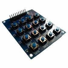
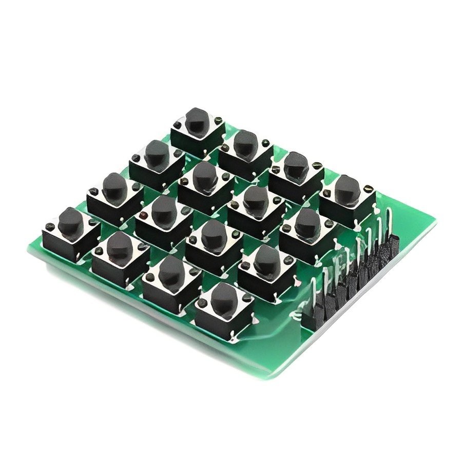
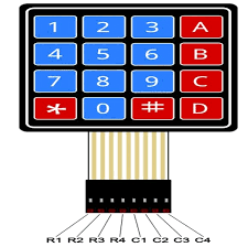
4 x 4

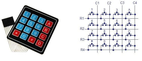
Besides 4X3 the 4x4 keypad is also available in which there are 4 columns and 4 rows. In this besides the numeric values alphabets A, B , C , D are also available in the last column . This keypad module finds application in the security system , industrial control system applications, data entry systems etc.

How does Keypad Modules works ?

The module usually consists of graphic overlay the part of the module that is visible to the user, It is usually made of polycarbonate or polyester materials that are highly customizable depending on the requirement . The material used makes the printed character to last longer.

It also consists of  an internal polymer layer which house the internal circuitry and protects from electric discharge and is also heat and water resistant 

Inside the polymer layer is the button mesh layer usually made of stainless steel dome like structure and second layer of embossed circuitry usually made by printing copper or silver oxide with some dielectrics to prevent short circuit

Both these layers are halves of the internal circuitry that completes the circuit when the user presses the button which sends a signal to one of 8 pins connected to the end of the ribbon.

Use cases of Keypad Module

How to connect Keypad Modules with Mitrocontrollers

The keypad modules can be used in both polling as well as interrupts mode. In polling mode the CPU checks the I/O readiness every clock cycle wasting processor-cycles  by checking the command-ready bit of the device. Whereas in interrupt mode the processor is only disturbed when the interrupt occurs and executes the command in the interrupt handler.

POLLING MODE

The 4 rows of the keypad module are used in GPIO input mode , whereas the 4 columns are used in GPIO output  mode . All the 4 column lines are given a GPIO high , the row lines on the other hand detect the location of the press . When a button is pressed the particular row indicates a high and since the column to which the pressed button belongs to is already high we can read the coordinates in the microcontroller pin . But this requires the microcontroller resources as continuous monitoring is done to check the device’s state

INTERRUPT MODE

In interrupt mode the matrix of the keypad module consisting of 4 rows and 4 columns is divided such that 4 columns are used in GPIO output mode whereas the 4 rows are used in interrupt mode . The 4 columns are by default left HIGH , when a key is pressed it then raises the interrupt of that particular row . The location of the pressed button is detected by the MCU and  then ISR  transfers the operation to interrupt handler in which task can be assigned for MCU to do.  

Author

Kunal

Leave a comment

Stay Updated With Us

Error: Contact form not found.

      Blog