
In the last blog we discussed what a keypad module is . In this blog we will be discussing how to interface a 4×4 membrane type keypad module with stm32 microcontroller. Although the keypad module can be configured using both polling and interrupt methods , in this blog we will be discussing the interrupt method as it takes less CPU cycles , also since interrupt doesn’t require constant CPU attention. Keypad module along with stm32 microcontroller finds applications in industrial machines as well various projects such as bluetooth door lock , scientific calculator etc.
The keypad module consists of 3 layers:-
- The top layer is made of polymer which usually is the printed graphic overlay . It defines the function of each button in the keypad module . It is heat and water resistant and also prevents from electric discharge.
- The middle layer that usually consists of dome shaped stainless buttons which upon touch makes contact with the bottom layer completing the circuitry.
- The bottom layer consists of printed circuitry made of conductive material such as silver or copper oxide. When a key is pressed the dome shaped buttons make contact which completes the circuit and this information is conveyed to microcontroller in the form of signal by the external ribbon.
The 4×4 keypad module chosen by us consists of numbers from 0 to 9 along with 2 characters ‘*’ and ‘#’ in the first 3 columns while the last column consists of alphabets A, B ,C , D.
The internal circuit diagram of the keypad module
- Internal Circuit
- Working
- Circuit Diagram
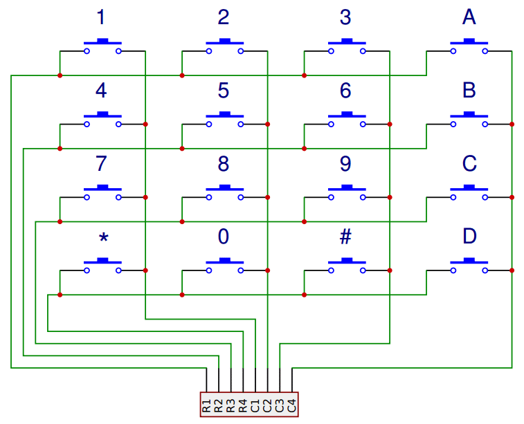
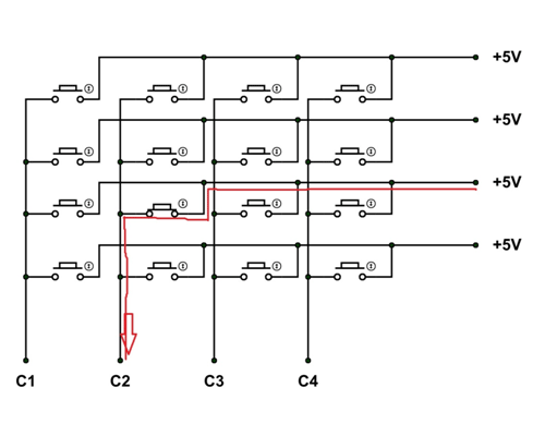
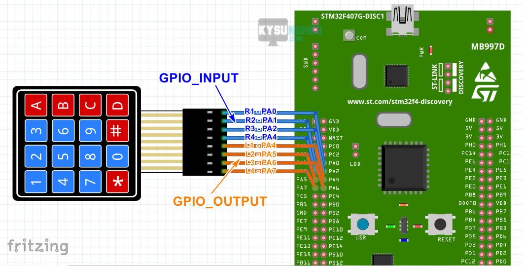
- As can be seen one end of each button is connected to a wire that is then connected to the connector pin as row and other end is connected to another wire which is the column wire. Both the row and column wires helps us pinpoint the button that is pressed.
- The connection are then made to the MCU in which the row part is configured as GPIO output and written high in our case this will be PA15, PB3, PB4 , PB5 pins the column part is then written as GPIO EXTI interrupt which will get triggered in case of a button push , this will be PB6,PB7,PB8,PB9 in our case .
- As can be seen in the figure since each row from one side is already HIGH once the connection is made by pressing the button this is read by the MCU pins PB6,PB7,PB8,PB9 and the interrupt is raised which is detected in the rising edge.
- Besides the keypad module connection UART1 is also enable as PA9 as TX and PA10 as RX
- This will be used to display the button pressed when the interrupt is fired using teraterm or similar software.
ALGORITHM
Configure pins PA15,PB3,PB4,PB5 as output pins with no pull up and low frequency
Configure pins PB6, PB7,PB8, PB9 as interrupt pins with no pull up and interrupt detection on the rising edge
Set the NVIC priority as 0 and enable IRQ
Incoming interrupts are handled using EXTI callback function
Initialize the UART1 function , configure the parameters and select PA9 as tx and PA10 as RX
Hal tick function is called to use key debouncing and prevent unwanted input noise from the buttons
2 variables currentMillis and previousMillis are declared which prevents extra activations or slow functions from triggering the interrupts this is done by subtracting the former from latter and the difference should be greater than 10
Each row is written GPIO 1 and checked if the corresponding column is gpio 1 as well. in case both the conditions are satisfied the interrupt is raised and a keypress is detected
The keypressed is displayed on Teraterm or similar software using UART1
SOFTWARE CONFIGURATION

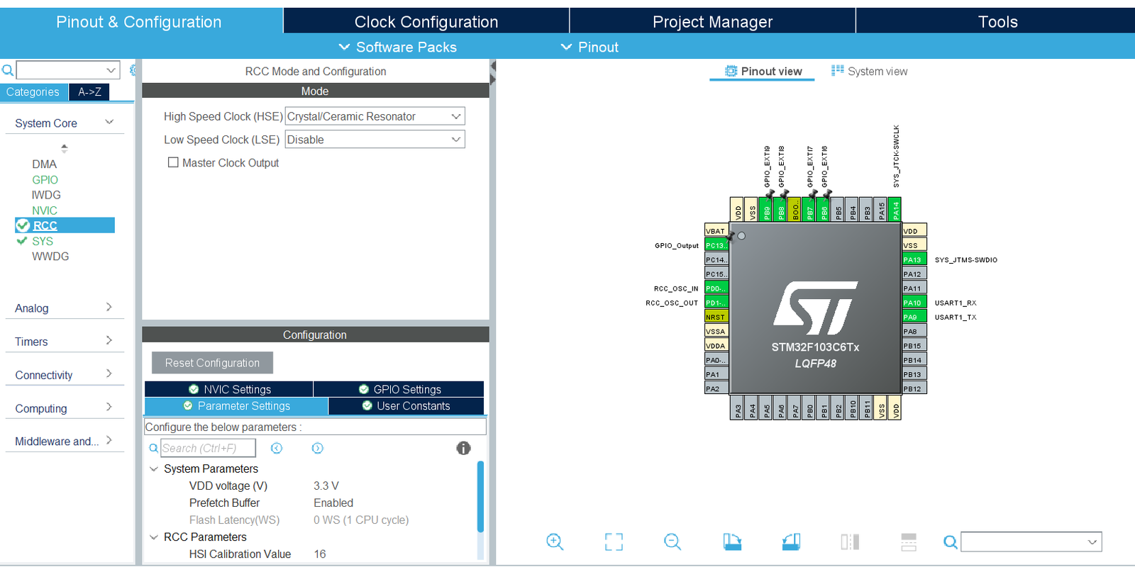
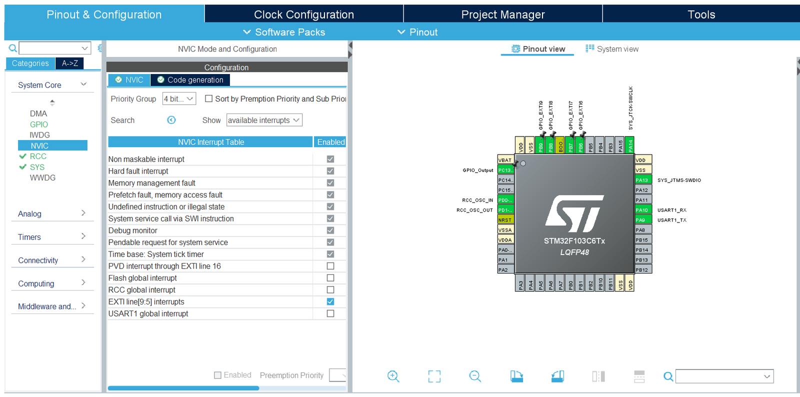
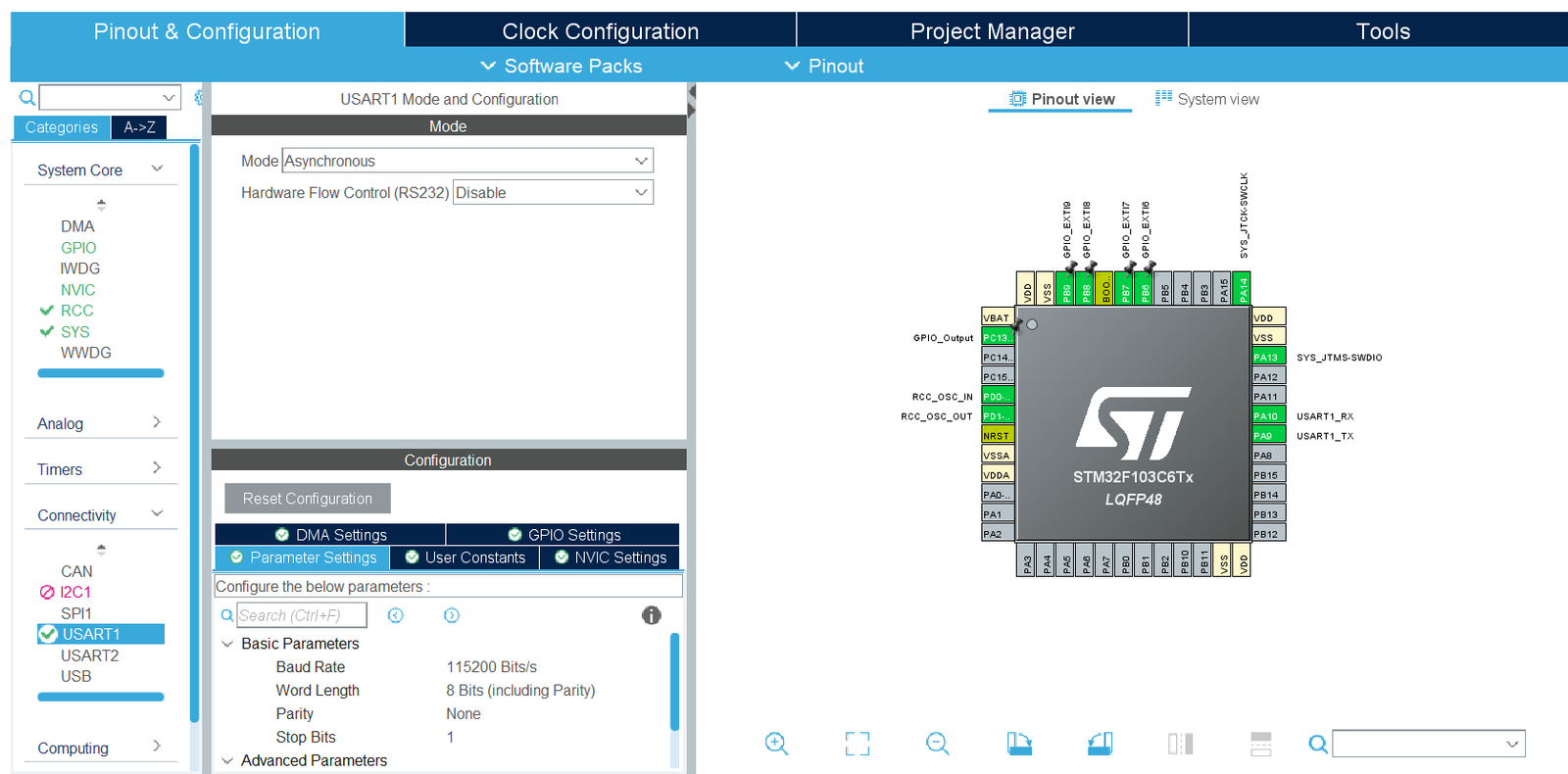
Open the stm32cube ide and configure the sys mode, select the debug as serial wire and time base source as systick . In the GPIO section select the pins PA15, PB3,PB4, PB5 as output pins set parameters to default which is GPIO pins to no pull and operations at low frequency .
Next select the pins PB6,PB7,PB8,PB9 as EXTI interrupt pins also in the NVIC section enable the line EXTI line [9:5] interrupts .Also configure the GPIO EXTI as interrupt rising which would read the occurrence of the interrupt on the rising edge of the wave and operation as low frequency .
The NVIC priority is set to 0 (the highest) and the IRQ is enabled. All the button or key presses are handled by HAL_GPIO_EXTI_Callback function in which the keydebouncing is applied and each row is written GPIO HIGH incase a button press the respective column goes high as well raising the interrupt and the corresponding key is displayed using UART .for eg-The button press such as key 9 is detected when both PB3 and PB7 is HIGH as due to the press a connection is made and an interrupt is raised.
Also in the connectivity section select the UART1 set the parameters such as mode to asynchronous , baud rate 115200, Word-length as 8 bits , Stop bits as 1 , mode as TX and RX , hardware flow control as none and oversampling rate as 16 . The UART1 has pin PA9 as TX and PA10 as RX . The uart is used to display the key that is pressed on a teraterm or similar software with baud rate set to 115200
SOFTWARE CONFIGURATION
CODE EXPLANATION
Intially include the library stdio.h and string.h that helps with sprintf functions and string functions . Next create a buffer that is char type array which stores the keypress character to display on the teraterm via uart.Initialize the uart next as uart1 and also gpio structure . Now the 32 bit variables previousMillis and currentMillis is declared which helps debouncing
Next in the main function the system clock configure function is called along with the UART1 and GPIO function that helps in initializing the configured peripherals .Next set the row pins PA15,PB3,P4,PB5 are set as HIGH.
Finally in the GPIO_EXTI_Callback the currentMillis function is assigned the time using HAL_GetTick function .The code enters the if condition when currentMillis and previousMillis function has difference greater than 10 sec as the previousMillis is assigned the value present in currentMillis at the end of the EXTI_Callback function.After entering the if condition each row is pulled HIGH simultaneously and in case of the button press the column is pulled HIGH which triggers the respective interrupt pin and the another if condition is satisfied in which the command to display the respective key is given .The sprintf function saves the keypressed and the HAL_Transmit function transmits the content of the buffer using UART1.
-
Function name
GPIO_PinState HAL_GPIO_ReadPin (GPIO_TypeDef * GPIOx, uint16_t GPIO_Pin)
-
Function Description
This API is used to read the data from the GPIO pins to zero in to the location of the button that is pressed.
-
Parameters
(1) GPIOX- This parameter is used to select the port of the given pin {here X=A, B ,C} (2) GPIO_Pin - This parameter is used to select the pin no {Pin no = 0 to 15}.
-
Return value
-
GPIO_Value
Usage
-
Function name
Void GPIO_EXTI_Callback (uint16_t GPIO_Pin)
-
Function Description
This API is used as an EXTI lines detection callback which detects if an interrupt has occurred and performs the task assigned to it.
-
Parameters
GPIO_Pin- Specifies the pin to which EXTI is connected
-
Return value
None
-
GPIO_Value
Usage
-
Function name
int sprintf(char *str, const char *string,...);
-
Function Description
This function is used to store the output in character buffer which is then printed on the console using HAL_UART_Transmit.
-
Parameters
Buffer , String , Variable
-
Return value
int
-
GPIO_Value
Usage
-
Function name
GPIO_PinState HAL_GPIO_ReadPin (GPIO_TypeDef * GPIOx, uint16_t GPIO_Pin)
-
Function Description
This API is used to read the data from the GPIO pins to zero in to the location of the button that is pressed.
-
Parameters
(1) GPIOX- This parameter is used to select the port of the given pin {here X=A, B ,C} (2) GPIO_Pin - This parameter is used to select the pin no {Pin no = 0 to 15}.
-
Return value
-
GPIO_Value
Usage
-
Function name
void HAL_GPIO_Init(GPIO_TypeDef *GPIOx, GPIO_InitTypeDef *GPIO_Init)
-
Function Description
This API is used to configure the GPIO pin methods such as Pin no , Mode, Pull , Speed etc of the selected port
-
Parameters
GPIOX -This parameter is used to select the port of the given pin {here X=A, B , C} GPIO_Init- this is a pointer to the structure GPIO_InitTypeDef that is used to configure the pin according to the values specified in the members
-
Return value
None
-
GPIO_Value
Usage
-
Function name
static void MX_GPIO_Init(void)
-
Function Description
This function is used to initialize the given GPIO peripheral which includes enabling the clock , selecting the default state of a given pin , initializing the structure and configuring the method of the given pin.
-
Parameters
None
-
Return value
None
-
GPIO_Value
Usage
-
Function name
static void MX_USART1_UART_Init(void)
-
Function Description
This function is used to initialize the USART1 function and is also responsible for initializing the uart1 instance and configure its members such as baudrate , wordlength , parity , hardware flow control, mode , stop bits etc
-
Parameters
None
-
Return value
None
-
GPIO_Value
Usage