
 STMicroelectronics is a leading provider of semiconductor solutions that are seamlessly integrated into billions of electronic devices used by people worldwide on a daily basis.
The semiconductor company builds products, solutions, and ecosystems that enable smarter mobility, more efficient power and energy management, and the wide-scale deployment of the Internet of Things and connectivity technologies. To know more about STMicroelectronics refer to its website: www.st.com.
Going back in history, ST was formed in 1987 by the merger of two government-owned semiconductor companies: Italian SGS Microelettronica (where SGS stands for Società Generale Semiconduttori, “Semiconductors’ General Company”), and French Thomson Semiconductors, the semiconductor arm of Thomson.
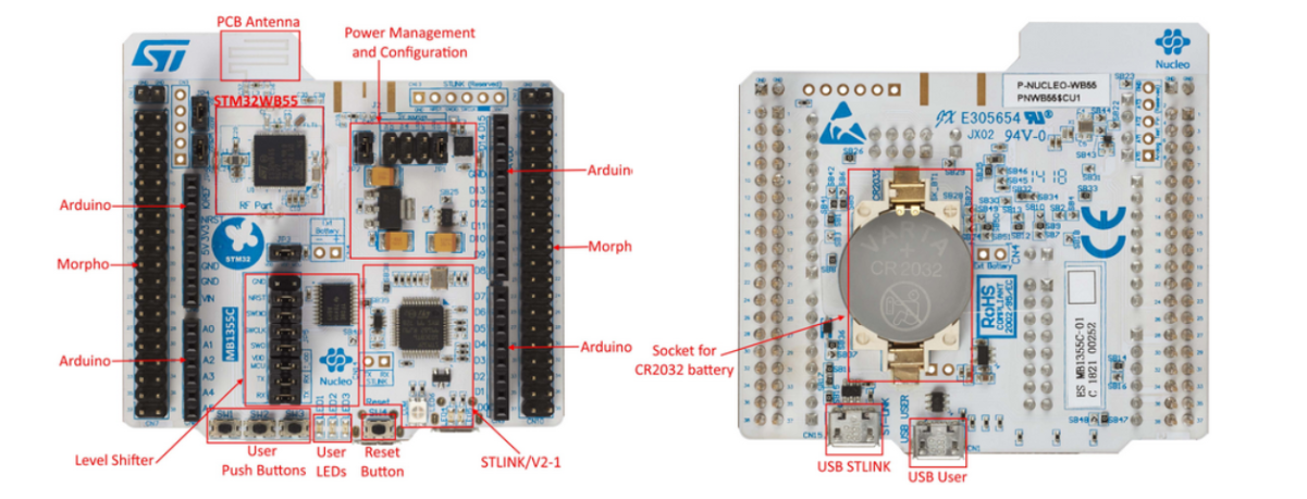
In this blog, we are going to start with ST IoT-based Nucleo Board STm32WB55.
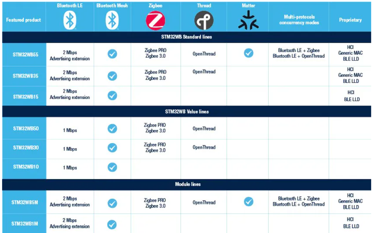
The STM32WB55xx and STM32WB35xx are advanced multiprotocol wireless devices that boast ultra-low-power consumption. These devices are equipped with a powerful and efficient radio that is compliant with the Bluetooth® Low Energy SIG specification 5 and IEEE 802.15.4-2011 (Zigbee). Additionally, they feature a dedicated Arm® Cortex®-M0+ processor that handles all real-time low-layer operations.
These cutting-edge devices are perfect for a wide range of applications that require reliable and efficient wireless communication. Whether you’re working on a smart home project, a wearable device, or an industrial automation system, the STM32WB55xx and STM32WB35xx are the ideal choices.

With their advanced features and capabilities, these devices are sure to revolutionize the way we think about wireless communication. So why wait? Start exploring the possibilities today and discover what the STM32WB55xx and STM32WB35xx can do for you!
The devices have been meticulously crafted to operate on minimal power and are built around the high-performance Arm® Cortex®-M4 32-bit RISC core, which can operate at a frequency of up to 64 MHz. This core boasts a Floating-point unit (FPU) single precision that supports all Arm® single-precision data-processing instructions and data types. Additionally, it is equipped with a full set of DSP instructions and a memory protection unit (MPU) that enhances application security.
These devices have been designed with the utmost care and attention to detail, ensuring that they are not only efficient but also highly effective. The Arm® Cortex®-M4 32-bit RISC core is a powerful tool that enables these devices to perform at an exceptional level, while the FPU single precision and DSP instructions provide unparalleled accuracy and precision. Furthermore, the memory protection unit (MPU) ensures that your applications are secure and protected from any potential threats.
Enhanced inter-processor communication is provided by the IPCC with six bidirectional channels. The HSEM provides hardware semaphores used to share common resources between the two processors.
The devices embed high-speed memories (up to 1 Mbyte of flash memory for STM32WB55xx, up to 512 Kbytes for STM32WB35xx, up to 256 Kbytes of SRAM for STM32WB55xx, 96 Kbytes for STM32WB35xx), a Quad-SPI flash memory interface (available on all packages) and an extensive range of enhanced I/Os and peripherals. 
Architecture
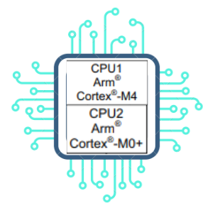
The host application is housed on an Arm® Cortex®-M4 CPU (named CPU1) that connects with a generic microcontroller subsystem.
The RF subsystem is made up of a specialized Arm® Cortex®-M0+ microprocessor (named CPU2), Bluetooth Low Energy and 802.15.4 digital MAC blocks, an RF analog front end, and proprietary peripherals. All Bluetooth Low Energy and 802.15.4 low-layer stack functions are handled by the RF subsystem, which limits communication with the CPU1 to high-level exchanges.
Some functions are shared between the RF subsystem CPU (CPU2) and the Host CPU (CPU1):
- Flash memories
- SRAM1, SRAM2a, and SRAM2b (SRAM2a can be retained in Standby mode)
- Security peripherals (RNG, AES1, PKA)
- Clock RCC
- Power control (PWR)
Memories
2.1. Adaptive real-time memory accelerator (ART Accelerator)
The ART Accelerator is a memory accelerator optimized for STM32 industry-standard Arm® Cortex®-M4 processors. It balances the inherent performance advantage of the Arm® Cortex®-M4 over flash memory technologies.
To release the processor near 80 DMIPS performance at 64 MHz, the accelerator implements an instruction prefetch queue and branch cache, which increases program execution speed from the 64-bit flash memory. Based on CoreMark benchmark, the performance achieved thanks to the ART accelerator is equivalent to 0 wait state program execution from flash memory at a CPU frequency up to 64 MHz.
2.2. Memory protection unit
In order to prevent one task from unintentionally corrupting the memory or resources used by any other active task, the memory protection unit (MPU) is used to manage the CPU1’s accesses to memory. This memory area is organized into up to eight protected areas.
The MPU is especially helpful for applications where some critical or certified code must be protected against the misbehavior of other tasks. It is usually managed by an RTOS (real-time operating system).
2.3. Embedded flash memory
The STM32WB55xx and STM32WB35xx devices feature, respectively, up to 1 Mbyte and 512 Kbytes of embedded flash memory available for storing programs and data, as well as some customer keys.
2.4. Embedded SRAM
The STM32WB55xx devices feature up to 256 Kbytes of embedded SRAM, split in three blocks:
- SRAM1: up to 192 Kbytes mapped at address 0x2000 0000
- SRAM2a: 32 Kbytes located at address 0x2003 0000 also mirrored at 0x1000 0000, with hardware parity check (this SRAM can be retained in Standby mode)
- SRAM2b: 32 Kbytes located at address 0x2003 8000 (contiguous with SRAM2a) and mirrored at 0x1000 8000 with hardware parity check.
Security and Safety
 The STM32WB55xx contain many security blocks both for the Bluetooth Low Energy or IEEE 802.15.4 and the Host application. It includes:
- Customer storage of the Bluetooth Low Energy and 802.15.4 keys
- Secure flash memory partition for RF subsystem-only access
- Secure SRAM partition, that can be accessed only by the RF subsystem
- True random number generator (RNG)
- Advance encryption standard hardware accelerators (AES-128bit and AES-256bit, supporting chaining modes ECB, CBC, CTR, GCM, GMAC, CCM)
- Private key acceleration (PKA)
- Cyclic redundancy check calculation unit (CRC)
True random number generator (RNG)
The devices embed a true RNG that delivers 32-bit random numbers generated by an integrated analog circuit.
RF Subsystem

The STM32WB55xx embeds an ultra-low power multi-standard radio Bluetooth Low Energy and 802.15.4 network processor, compliant with Bluetooth specification 5.3 and IEEE® 802.15.4-2011. The Bluetooth Low Energy features 1 Mbps and 2 Mbps transfer rates, supports multiple roles simultaneously acting at the same time as Bluetooth Low Energy sensor and hub device.
The Bluetooth Low Energy stack and 802.15.4 Low Level layer run on an embedded Arm® Cortex®-M0+ core (CPU2). The stack is stored on the embedded flash memory, which is also shared with the Arm® Cortex®-M4 (CPU1) application, making it possible in-field stack update.
4.1. RF Front-End Block Diagram
The RF front-end is based on a direct modulation of the carrier in Tx, and uses a low IF architecture in Rx mode. Thanks to an internal transformer at RF pins, the circuit directly interfaces the antenna (single ended connection, impedance close to 50 Ω).
In Transmit mode, the maximum output power is user selectable through the programmable LDO voltage of the power amplifier. A linearized, smoothed analog control offers clean power ramp-up.
In Receiving mode the circuit can be used in standard high performance or in reduced power consumption (user programmable). The Automatic gain control (AGC) is able to reduce the chain gain at both RF and IF locations, for optimized interference rejection.
4.2. BLE Description
It integrates a 2.4 GHz RF transceiver and a powerful Cortex®-M0+ core, on which a complete power-optimized stack for Bluetooth Low Energy protocol runs, providing master / slave role support
- GAP: central, peripheral, observer or broadcaster roles
- ATT/GATT: client and server
- SM: privacy, authentication and authorization
- L2CAP
- Link layer: AES-128 encryption and decryption
In addition, according to Bluetooth specification 5.3, the Bluetooth Low Energy block provides:
- Multiple roles simultaneous support
- Master/slave and multiple roles simultaneously
- LE data packet length extension (making it possible to reach 800 kbps at application level)
- LE privacy 1.2
- LE secure connections
- Flexible Internet connectivity options
- High data rate (2 Mbps)
The device also supports Piconet and Scatternet.
Ultra-low-power sleep modes and very short transition time between operating modes result in very low average current consumption.
4.3. Zigbee (802.15.4) Description
The STM32WB55xx embeds a dedicated 802.15.4 hardware MAC:
- Support for 802.15.4 release 2011
- Advanced MAC frame filtering; hardwired firewall: Programmable filters based on source/destination addresses, frame version, security enabled, frame type
- 256-byte RX FIFO; Up to 8 frames capacity, additional frame information (timing, mean RSSI, LQI)
- 128-byte TX FIFO with retention
- Automatic frame acknowledgment, with programmable delay
- Advanced channel access features
- Configuration registers with retention available down to Standby mode for software/auto-restore
- Autonomous sniffer, wake-up based on timer or CPU2 request
- Automatic frame transmission/reception/sleep periods, Interrupt to the CPU2 on particular events
Low Power Modes
- Sleep
In Sleep mode, only the CPU1 is stopped. All peripherals, including the RF subsystem, continue to operate and can wake up the CPU when an interrupt/event occurs.
- Low-power run
This mode is achieved with VCORE supplied by the low-power regulator to minimize the regulator operating current. The code can be executed from SRAM or from the flash memory, and the CPU1 frequency is limited to 2 MHz. The peripherals with independent clock can be clocked by HSI16. The RF subsystem is not available in this mode and must be OFF.
- Low-power sleep
This mode is entered from the low-power run mode. Only the CPU1 clock is stopped. When wake-up is triggered by an event or an interrupt, the system reverts to the low-power run mode. The RF subsystem is not available in this mode and must be OFF.
- Stop 0, Stop 1 and Stop 2
Stop modes achieve the lowest power consumption while retaining the content of all the SRAM and registers. The LSE (or LSI) is still running. The RTC can remain active (Stop mode with RTC, Stop mode without RTC). Some peripherals with wake-up capability can enable the HSI16 RC during Stop modes to detect their wake-up condition. Three modes are available: Stop 0, Stop 1 and Stop 2.
In Stop 2 mode, most of the VCORE domain is put in a lower leakage mode.
Stop 1 offers the largest number of active peripherals and wake-up sources, a smaller wake-up time but a higher consumption than Stop 2.
In Stop 0 mode the main regulator remains ON, allowing a very fast wake-up time but with higher consumption. In these modes the RF subsystem can wait for incoming events in all Stop modes. The system clock when exiting from Stop 0, Stop1 or Stop2 modes can be either MSI up to 48 MHz or HSI16 if the RF subsystem is disabled.
- Standby
The Standby mode is used to achieve the lowest power consumption with BOR. The internal regulator is switched off so that the VCORE domain is powered off. The RTC can remain active (Standby mode with RTC).
After entering Standby mode, SRAM1, SRAM2b and register contents are lost except for registers in the Backup domain and Standby circuitry. Optionally, SRAM2a can be retained in Standby mode, supplied by the low-power regulator (Standby with 32 KB SRAM2a retention mode).
The system clock after wake-up is 16 MHz, derived from the HSI16. If used, the SMPS is restarted automatically. In this mode the RF can be used.
- Shutdown
This mode achieves the lowest power consumption. The internal regulator is switched off so that the VCORE domain is powered off. The RTC can remain active (Shutdown mode with RTC, Shutdown mode without RTC). The BOR is not available in Shutdown mode. No power voltage monitoring is possible in this mode, therefore the switch to Backup domain is not supported. SRAM1, SRAM2a, SRAM2b and register contents are lost except for registers in the Backup domain.
The system clock after wake-up is 4 MHz, derived from the MSI. In this mode the RF is no longer operational.
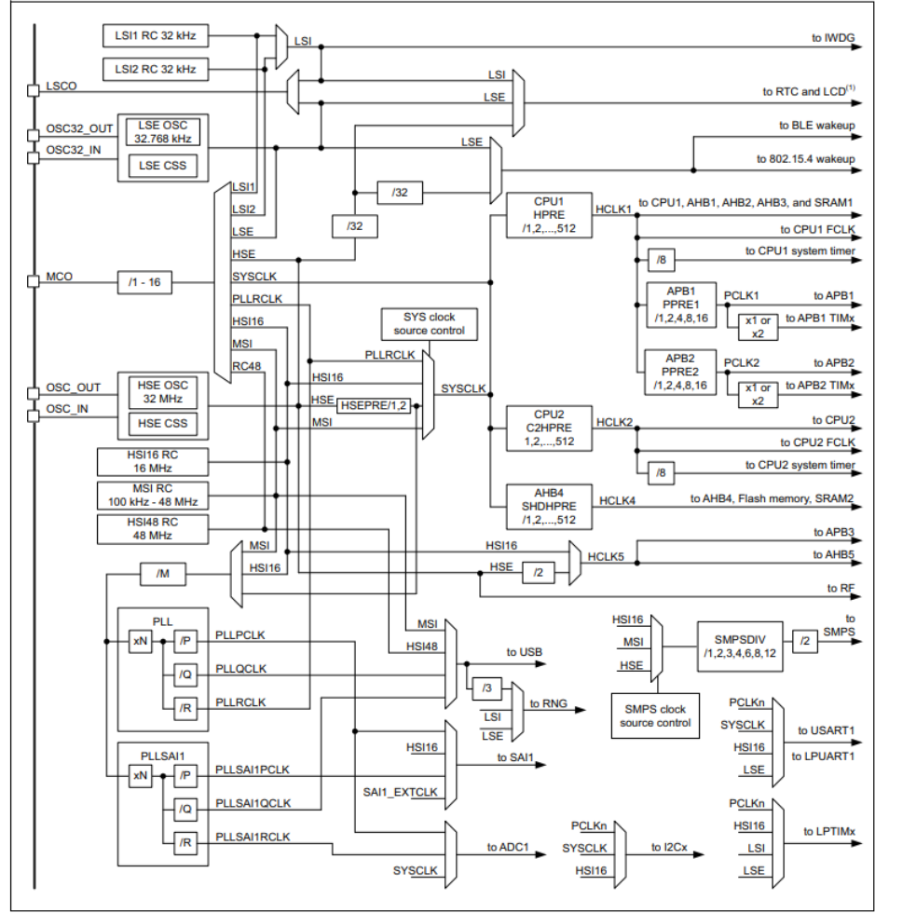
Clocks and Startup
 The STM32WB55xx device integrate several clock sources:
- LSE: 32.768 kHz external oscillator, for accurate RTC and calibration with other embedded RC oscillators
- LSI1: 32 kHz on-chip low-consumption RC oscillator
- LSI2: almost 32 kHz, on-chip high-stability RC oscillator, can be used by the RF subsystem instead of LSE
- HSE: high-quality 32 MHz external oscillator with trimming, needed by the RF subsystem
- HSI16: 16 MHz high accuracy on-chip RC oscillator
- MSI: 100 kHz to 48 MHz multiple speed on-chip low power oscillator, can be trimmed using the LSE signal
- HSI48: 48 MHz on-chip RC oscillator, for USB crystal-less purpose.
STM32 WB55 has Clock Controller, which has following features:
- Clock prescaler: to get the best trade-off between speed and current consumption, the clock frequency to the CPU and peripherals can be adjusted by a programmable prescaler • Safe clock switching: clock sources can be changed safely on the fly in run mode through a configuration register.
- Clock management: to reduce power consumption, the clock controller can stop the clock to the core, individual peripherals or memory.
- System clock source: four different clock sources can be used to drive the master clock SYSCLK.
- Auxiliary clock source: two ultralow-power clock sources that can be used to drive the LCD controller and the real-time clock.
- Peripheral clock sources: Several peripherals (RNG, SAI, USARTs, I2Cs, LPTimers, ADC) have their own independent clock whatever the system clock. Two PLLs, each having three independent outputs for the highest flexibility, can generate independent clocks for the ADC, the RNG and the SAI.
- Startup clock: after reset, the microcontroller restarts by default with an internal 4 MHz clock (MSI). The prescaler ratio and clock source can be changed by the application program as soon as the code execution starts.
- Clock security system (CSS): this feature can be enabled by software. If an HSE clock failure occurs, the master clock is automatically switched to HSI16 and a software interrupt is generated if enabled. LSE failure can also be detected and an interrupt generated.
GPIO
Each of the GPIO pins can be configured by software as output (push-pull or open-drain), as input (with or without pull-up or pull-down) or as peripheral alternate function. Most of the GPIO pins are shared with digital or analog alternate functions. Fast I/O toggling can be achieved thanks to their mapping on the AHB2 bus.
DMA

Direct memory access (DMA) is used to provide high-speed data transfer between peripherals and memory as well as between memories. Data can be quickly moved by DMA without any CPU action. This keeps CPU resources free for other operations.
Here the two DMA embeds inside the controllers have fourteen channels in total, a full cross matrix allows any peripheral to be mapped on any of the available DMA channels. Each DMA has an arbiter for handling the priority between DMA requests.
Interrupts and Events

9.1. NVIC (Nested Vectored Interrupt Controller)
The devices embed a nested vectored interrupt controller able to manage 16 priority levels, and handle up to 63 maskable interrupt channels plus the 16 interrupt lines of the Cortex®-M4 with FPU.
The NVIC benefits are the following:
- Closely coupled NVIC gives low latency interrupt processing
- Interrupt entry vector table address passed directly to the core
- Allows early processing of interrupts
- Processing of late arriving higher priority interrupts
- Support for tail chaining
- Processor state automatically saved
- Interrupt entry restored on interrupt exit with no instruction overhead
9.2. Extended Interrupts and Events Controller (EXTI)
The EXTI manages wake-up through configurable and direct event inputs. It provides wake-up requests to the Power control, and generates interrupt requests to the CPUx NVIC and events to the CPUx event input.
ADC
 The device embeds a successive approximation analog-to-digital converter with the following features:
- 12-bit native resolution, with built-in calibration.
- Up to 16-bit resolution with 256 oversampling ratio.
- 4.26 Msps maximum conversion rate with full resolution .
- Up to sixteen external channels and three internal channels: internal reference voltages, temperature sensor • Single-ended and differential mode inputs.
- Low-power design .
- Highly versatile digital interface.
Comparators (COMP)
The STM32WB55xx device embeds two rail-to-rail comparators with programmable reference voltage (internal or external), hysteresis, and speed (low-speed for low power) and with selectable output polarity.
The reference voltage can be one of the following:
- External I/O .
- Internal reference voltage or submultiple (1/4, 1/2, 3/4).
Touch Sensing Controller
The touch sensing controller provides a simple solution for adding capacitive sensing functionality to any application. Capacitive sensing technology is able to detect finger presence near an electrode which is protected from direct touch by a dielectric such as glass or plastic.
The main features of the touch sensing controller are the following:
- Robust surface charge transfer acquisition principle
- Supports up to 18 capacitive sensing channels
- Up to six capacitive sensing channels can be acquired in parallel offering a very good response time.
- Spread spectrum feature to improve system robustness in noisy environments.
- Full hardware management of the charge transfer acquisition sequence
- Programmable charge transfer frequency
- Programmable sampling capacitor I/O pin
- Programmable channel I/O pin.
- Programmable max count value to avoid long acquisition when a channel is faulty.
- Dedicated end of acquisition and max count error flags with interrupt capability .
- One sampling capacitor for up to three capacitive sensing channels to reduce the system components.
- Compatible with proximity, touch key, linear and rotary touch sensor implementation.
Liquid crystal display controller (LCD)
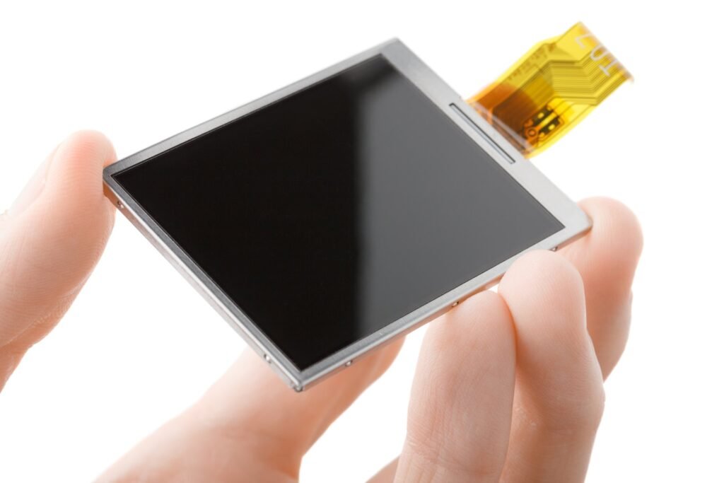
The STM32WB55xx devices embed an LCD controller with the following characteristics:
- Highly flexible frame rate control.
- Supports Static, 1/2, 1/3, 1/4 and 1/8 duty.
- Supports Static, 1/2, 1/3 and 1/4 bias.
- Double-buffered memory allows data in LCD_RAM registers to be updated at any time by the application firmware without affecting the integrity of the data displayed.
- Software selectable LCD output voltage (contrast) from VLCDmin to VLCDmax.
- No need for external analog components.
- The contrast can be adjusted using two different methods.
- Full support of low-power modes: the LCD controller can be displayed in Sleep, Low-power run, Low-power sleep and Stop modes, or can be fully disabled to reduce power consumption.
- Built in phase inversion for reduced power consumption and EMI (electromagnetic interference).
- Start of frame interrupt to synchronize the software when updating the LCD data RAM. • Blink capability.
Timers and watchdogs
The STM32WB55xx includes one advanced 16-bit timer, one general purpose 32-bit timer, two 16-bit basic timers, two low-power timers, two watchdog timers and a SysTick timer.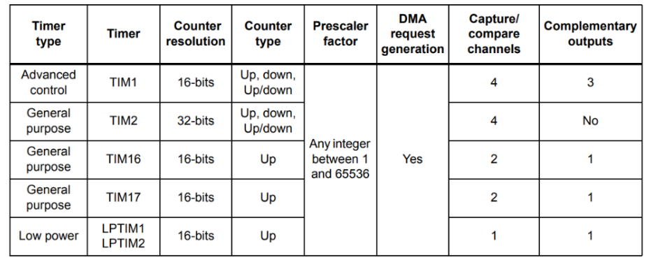
Real-time clock (RTC) and backup registers
The RTC is an independent BCD timer/counter, supporting the following features:
- Calendar with subsecond, seconds, minutes, hours (12 or 24 format), week day, date, month, year, in BCD (binary-coded decimal) format.
- Automatic correction for 28, 29 (leap year), 30, and 31 days of the month.
- Two programmable alarms.
- On-the-fly correction from 1 to 32767 RTC clock pulses. This can be used to synchronize it with a master clock.
- Reference clock detection: a more precise second source clock (50 or 60 Hz) can be used to enhance the calendar precision.
- Digital calibration circuit with 0.95 ppm resolution, to compensate for quartz crystal inaccuracy.
- Three anti-tamper detection pins with programmable filter.
- Timestamp feature, which can be used to save the calendar content. This function can be triggered by an event on the timestamp pin, or by a tamper event, or by a switch to VBAT mode.
- 17-bit auto-reload wake-up timer (WUT) for periodic events with programmable resolution and period.
The backup registers are 32-bit registers used to store 80 bytes of user application data when VDD power is not present. They are not reset by a system or power reset, or when the device wakes up from Standby or Shutdown mode.
Inter Integrated Circuit (I2C)
The I2C bus interface handles communications between the microcontroller and the serial I2C bus. It controls all I2C bus-specific sequencing, protocol, arbitration and timing.
The device has 2 I2C peripherals which supports:
- Slave and master modes, multimaster capability
- Standard-mode (Sm), with a bitrate up to 100 kbit/s
- Fast-mode (Fm), with a bitrate up to 400 kbit/s .
- Fast-mode Plus (Fm+), with a bitrate up to 1 Mbit/s and 20 mA output drive I/Os .
- 7-bit and 10-bit addressing mode, multiple 7-bit slave addresses .
- Programmable setup and hold times .
- Optional clock stretching.
UART
UART
The devices embed one universal synchronous receiver transmitter. and one Low-Power UART.
The USART is able to communicate at speeds of up to 4 Mbit/s.It provides hardware management of the CTS and RTS signals, and RS485 driver enable.
The USART has a clock domain independent from the CPU clock, allowing it to wake up the MCU from Stop mode using baud rates up to 200 kbaud. The wake up events from Stop mode are programmable and can be:
- the start bit detection
- any received data frame
- a specific programmed data frame.
The USART interface can be served by the DMA controller.
LP-UART
The device embeds one Low-Power UART, enabling asynchronous serial communication with minimum power consumption. The LPUART supports half duplex single wire communication and modem operations (CTS/RTS), allowing multiprocessor communication.
The LPUART has a clock domain independent from the CPU clock, and can wake-up the system from Stop mode using baud rates up to 220 kbaud. The wake up events from Stop mode are programmable and can be:
- the start bit detection
- any received data frame
- a specific programmed data frame.
Only a 32.768 kHz clock (LSE) is needed for LPUART communication up to 9600 baud. Therefore, even in Stop mode, the LPUART can wait for an incoming frame while having an extremely low energy consumption. Higher speed clock can be used to reach higher baud rates.
The LPUART interfaces can be served by the DMA controller.
SPI
Two SPI interfaces enable communication up to 32 Mbit/s in master and up to 24 Mbit/s in slave modes, in half-duplex, full-duplex and simplex modes. The 3-bit prescaler gives 8 master mode frequencies and the frame size is configurable from 4 bits to 16 bits. The SPI interfaces support NSS pulse mode, TI mode and Hardware CRC calculation.
The SPI interfaces can be served by the DMA controller.
Serial audio interfaces (SAI)
The device embeds a dual channel SAI peripheral that supports full duplex audio operation. The SAI bus interface handles communications between the microcontroller and the serial audio protocol.
The SAI peripheral supports:
- One independent audio sub-block that can be a transmitter or a receiver, with the respective FIFO
- 8-word integrated FIFOs
- Synchronous or asynchronous mode
- Master or slave configuration
- Clock generator to target independent audio frequency sampling when audio sub-block is configured in master mode
- Data size configurable: 8-, 10-, 16-, 20-, 24-, 32-bit
- Peripheral with large configurability and flexibility allowing to target as example the following audio protocol: I2S, LSB or MSB-justified, PCM/DSP, TDM, AC’97 and SPDIF out
- Up to 16 slots available with configurable size and with the possibility to select which ones are active in the audio frame
- Number of bits by frame may be configurable
- Frame synchronization active level configurable (offset, bit length, level) • First active bit position in the slot is configurable
- LSB first or MSB first for data transfer
- Mute mode
- Stereo/Mono audio frame capability
- Communication clock strobing edge configurable (SCK)
- Error flags with associated interrupts if enabled respectively.
- DMA interface with two dedicated channels to handle access to the dedicated integrated FIFO of the SAI audio sub-block.
QUADSPI
The Quad-SPI is a specialized communication interface targeting single, dual or quad SPI flash memories.
It can operate in any of the three following modes:
- Indirect mode: all the operations are performed using the QUADSPI registers
- Status polling mode: the external memory status register is periodically read and an interrupt can be generated in case of flag setting
- Memory-mapped mode: the external flash memory is mapped and is seen by the system as if it
Light Beige Sleek and Simple Blogger Personal Website by KsmaVideoEditor harsh gettobyte technp;pgies
Getting Hands-On with NXP eIQ: A “No Code” Starter Guide for Edge AI Developers
Introduction In a world driven by AI and IoT, deploying machine learning at the edge has become essential. NXP’s eIQ™
FRDM i.MX93 Demystified: The Hardware That Makes AI Work at the Edge
Imagine you’re handed a powerful little board, no bigger than your palm. At first glance, it looks like a jungle
How to Run AI on a Microcontroller or Microprocessor – A Beginner’s Guide to Edge AI
In the last few years, Edge AI has rapidly transformed how devices understand and interact with the world — without
Edge AI ToolKit: EiQ AI SDK
Introduction to EiQ In previous blogs, we’ve discussed in depth Edge AI, its features, advantages, and future scopes. Implementation of
