 In this blog we will be discussing another special functionality of GPIO pins I2C or Inter-Integrated Circuit or I2c functionality . I2C is a two wire interface or TWI which was developed by the Philips corporation for use in consumer products . It is a bidirectional bus that can be easily implemented in an IC process.I2C combines best features of SPI as well as UART it lets the user control multiple slaves via multiple masters which is useful when logging data to sd cards or displaying on LCD. Just like SPI the output data bits are synchronized to sampling of the clock shared by both the parties involved in the communication . The master always generates the clock.The protocol finds applications in hardware sensors or displays , reading memory ICs , communicating with microcontrollers , ADC or DACs.
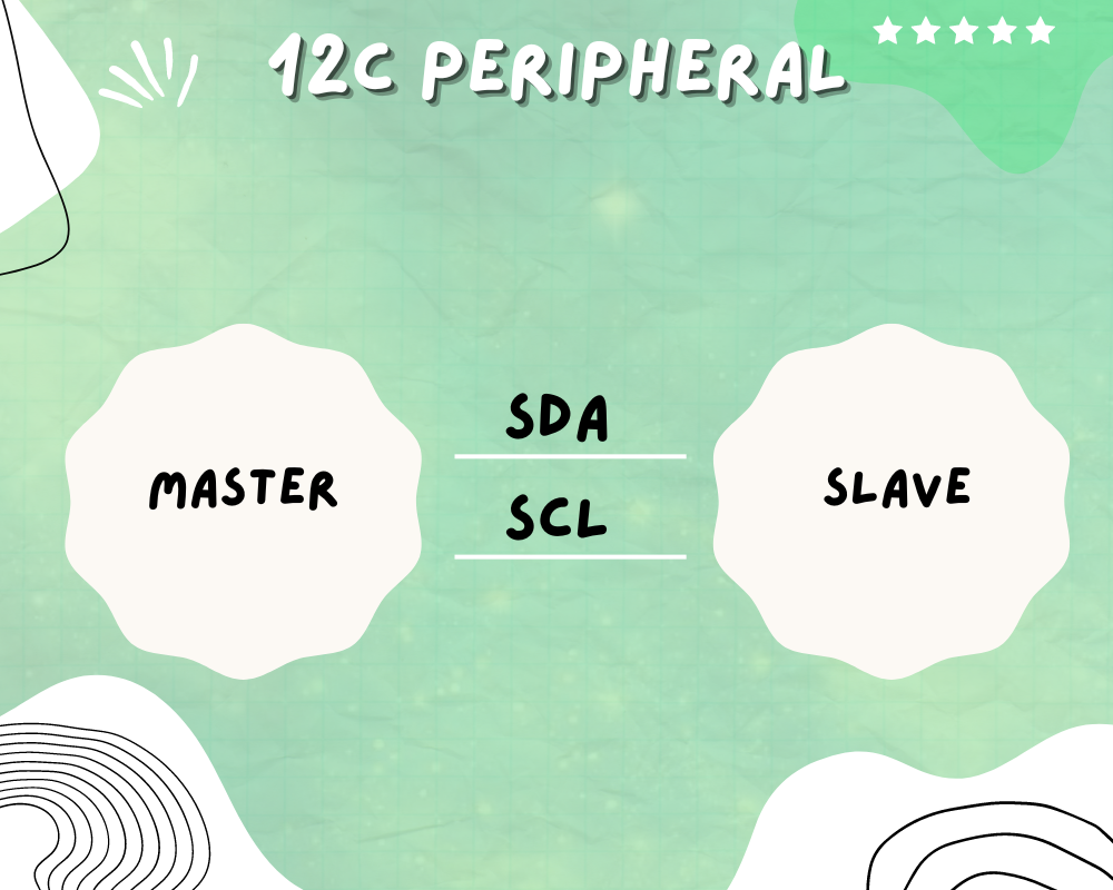
 I2C consists of 2 lines SCL and SDA
1.SCL (Serial Clock ) – For synchronizing data transfer between master and slave
2, SDA (Serial Data ) – The data transmission or receiving line
Multiple Master and Slave lines are connected to the SDA and SCL lines and both these lines are pulled up using resistors to Vdd (5v)
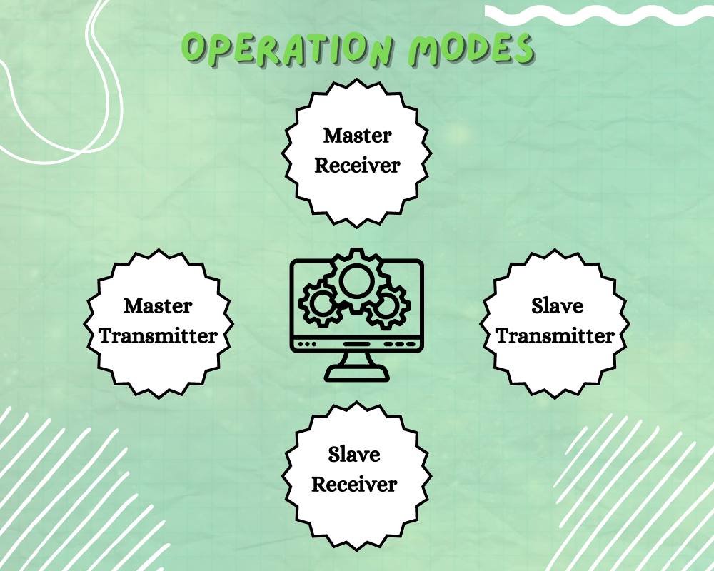
Operation Modes In I2C
- Master Transmitter
- Master Receiver
- Slave Transmitter
- Slave Receiver
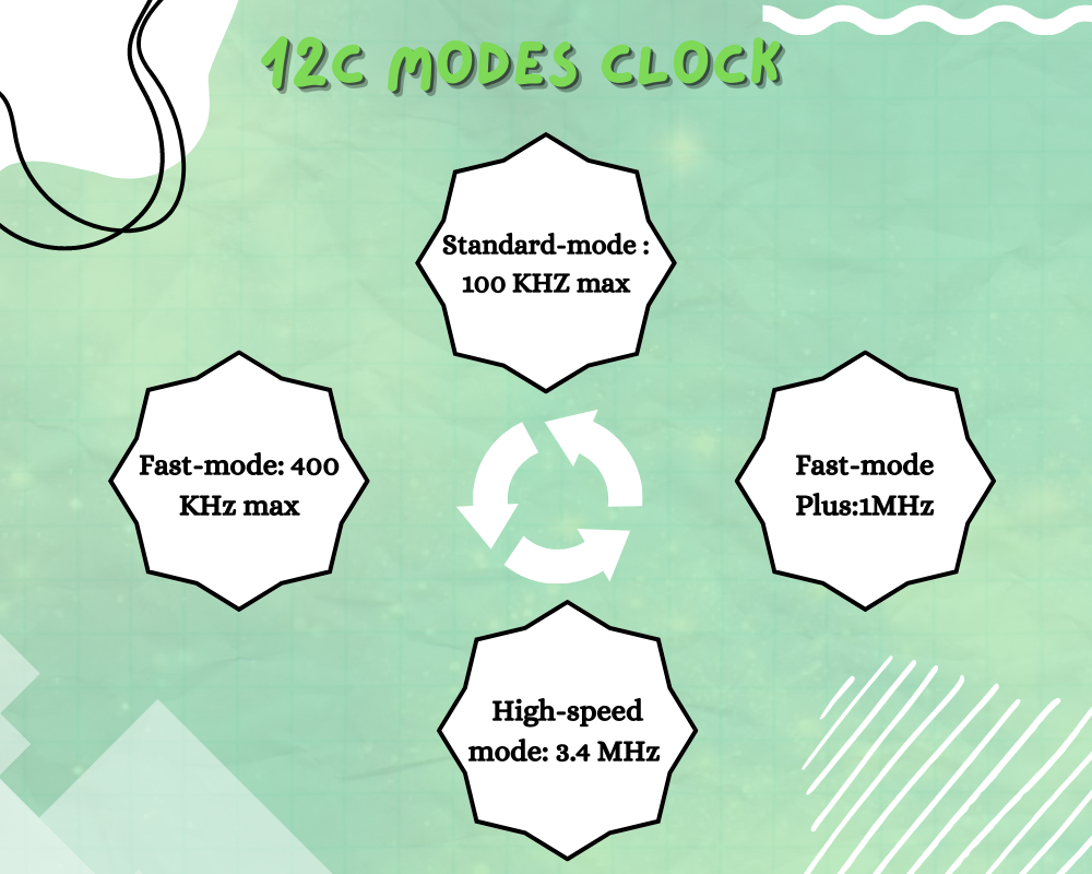
I2C Clock Speed
The speed of the I2C bus should be in reference to the one provided in the datasheet
The modes of I2C clock speed are as follows:-
- Standard-mode : 100 KHZ max
- Fast-mode: 400 KHz max
- Fast-mode Plus:1MHz
- High-speed mode: 3.4 MHz
I2C duty cycle specifies the ratio between Tlow and Thigh of the I2C SCL line
The values being:
I2C_DUTYCYCLE_2=2:1
I2C_DUTYCYCLE_16_9= 16:9
The desired clock speed can be achieved using the appropriate duty cycle to prescale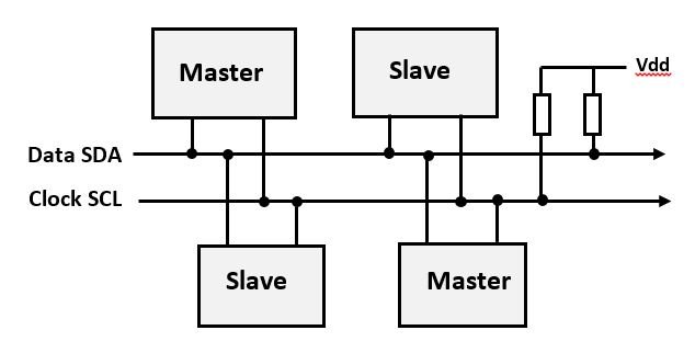


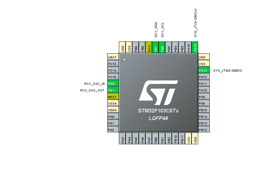
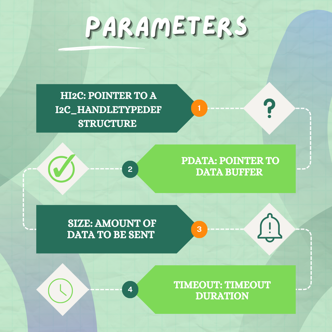
FIG 1- Selecting the SCL and SDA pin
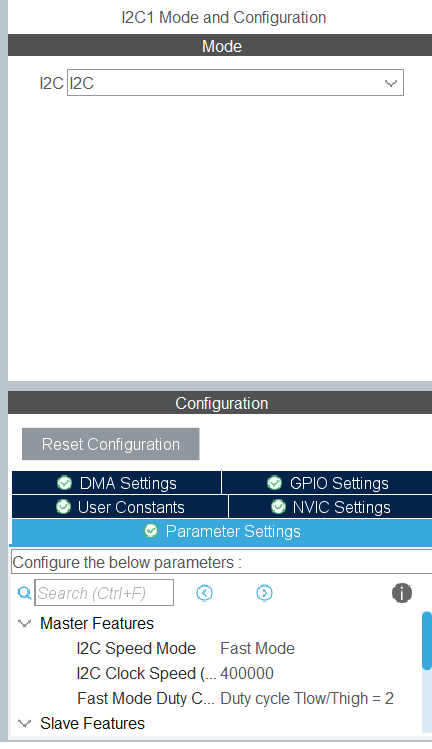
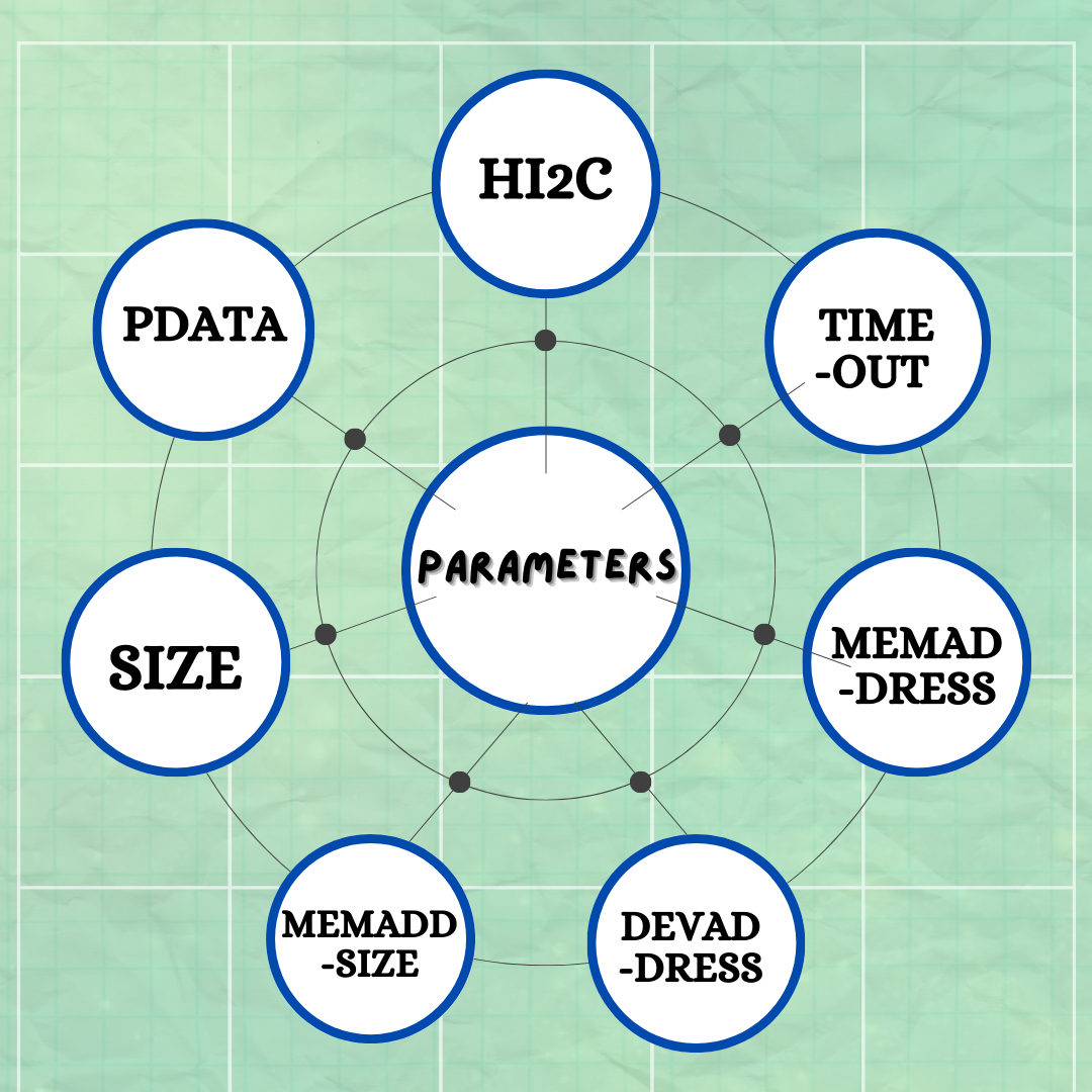
FIG 2 – Configuring the i2c parameters
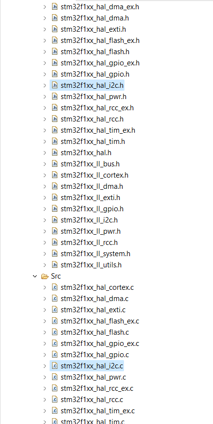
- Stm32f1xx_hal.c
- Stm32f1xx_hal_i2c.c
- Stm32f1xx_hal_i2c.h
The hal.c contains all the macros , function declarations , alternate function mapping of GPIO peripheral and Clock Configurations .The i2c.c file contains initialization and declaration of various low level registers , macros , static void functions , callback functions , configuration of various parameters of both master as well as slave . The i2c.h file contains all the enums , structure parameters such as clock speed , ownaddress declarations etc.It also contains the declaration of macros of the values that will be filled by the structure parameters such as duty cycle value .