So, in this blog we will be covering another alternate functionality of GPIO pins i.e SPI (Serial Peripheral Interface). Previously we hve covered following peripherals implementation in STM32F103 MCU’s.
- ADC(Analog To Digital Converter) in STM32F103
- UART Peripheral in STM32F103
- GPIO Peripheral in S32K144 MCU
- Clock Peripheral in STM32F103
- PWM on STM32F103
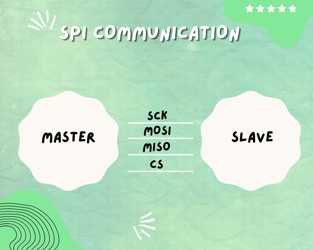 SPI is a synchronous and full duplex communication between a master and several slave devices. It is used in devices or sensors in which speed is a priority . It operates at data transmission rate 8 Mbits or more. The protocol uses 3 or usually 4 wires for data transmission and receiver .It is used by various sensors and modules such as OLED Display, BMP280 , RC522 , DAC , Shift Registers etc.
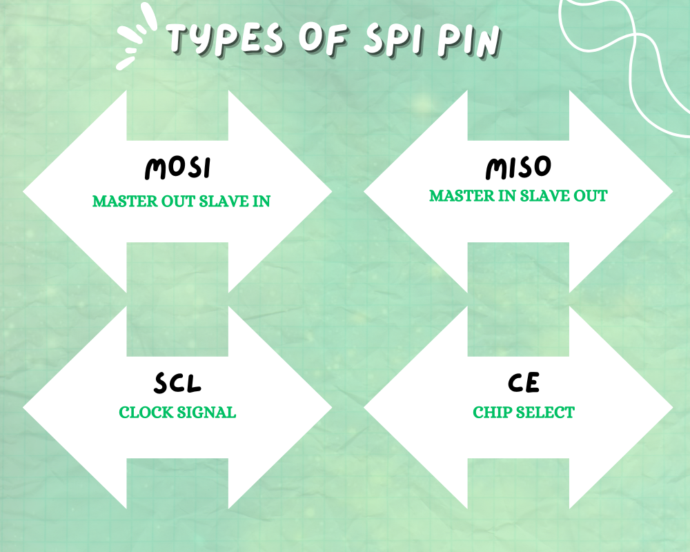 The SPI uses 2 pins for data transfer SDIN and SDO , SCLK clock for synchronization of data transfer between 2 chips, CE chip select that is used to initiate and terminate the data transfer.
SDI = MOSI
SDO = MISO
SCLK = SCK
CE = SS
Besides SPI communication the SPI interface can switch between I2S communication protocol that is a synchronous serial communication interface. It supports 4 audio standards including the I2S Philips standard, the MSB- and LSB-justified standards, and the PCM standard. The operating modes can be full duplex(4 wires) and half duplex (6 wires)

Multiple subnodes can be used with a single SPI main. The subnodes can be connected in regular mode or daisy-chain mode.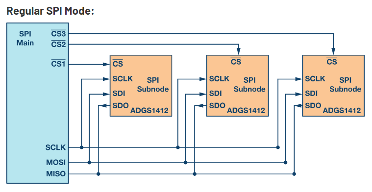
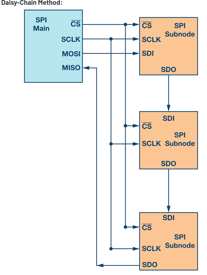
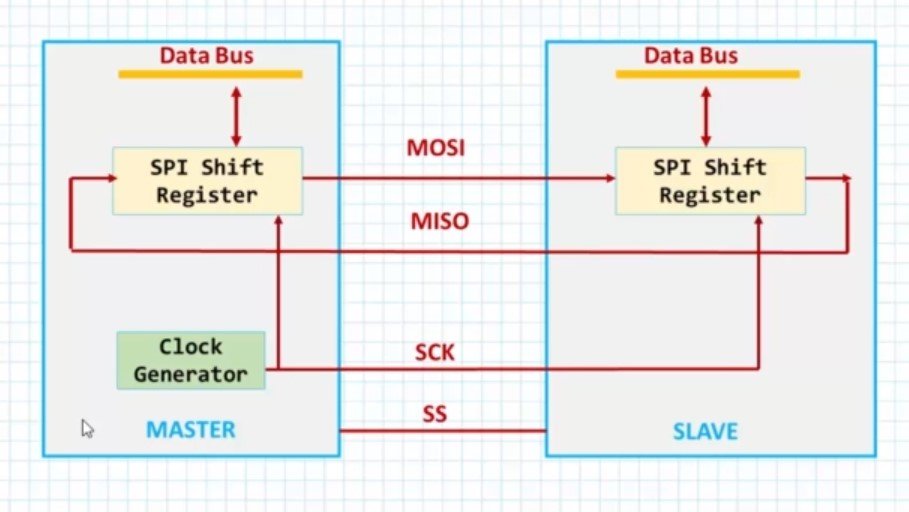
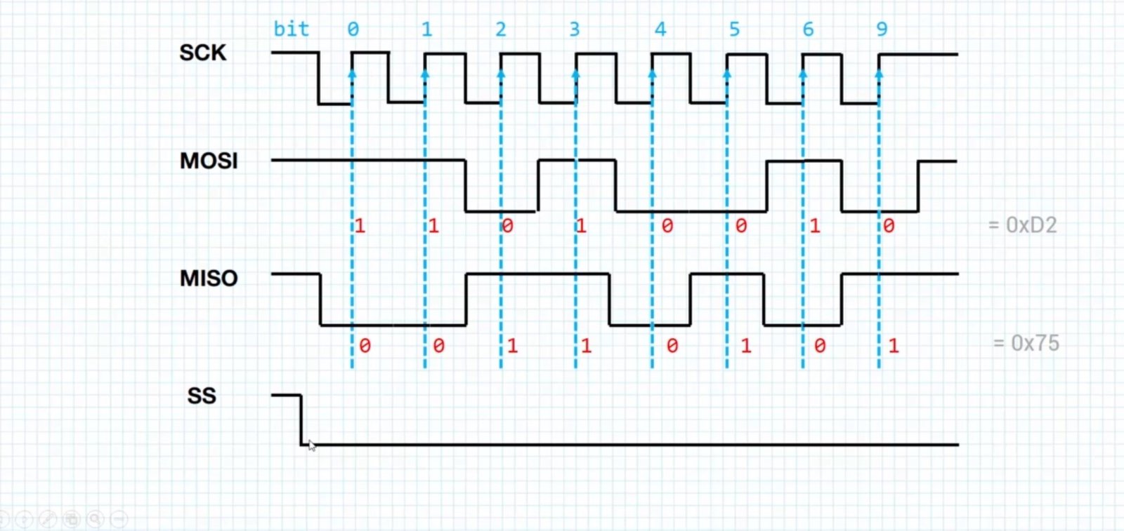
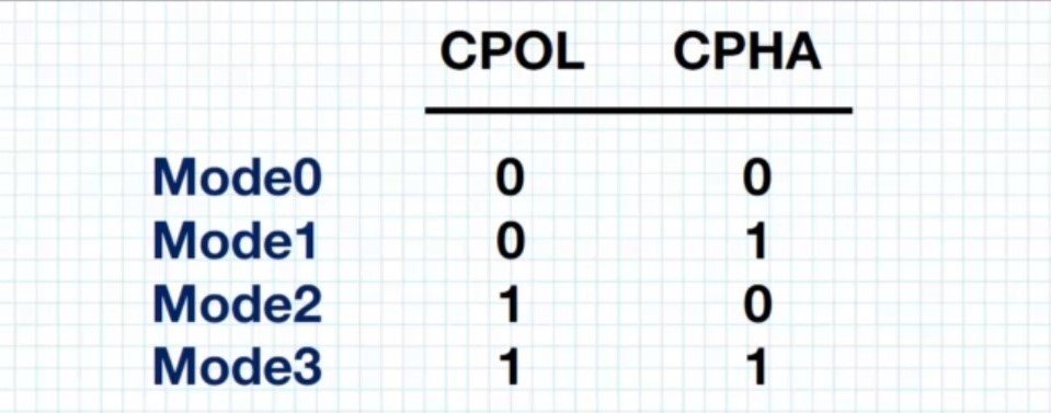
Before discussing about the various bus modes we will be discussing the clock phase and polarity i.e CPOL:Clock Polarity and CPHA:Clock Phase and it is the combination of CPOL and CPHA that is referred to as Bus Modes.
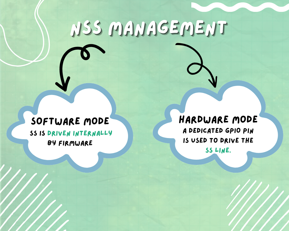 NSS line can to be driven via 2 modes
- Software Mode- SS is driven internally by firmware
- Hardware Mode – A dedicated GPIO pin is used to drive the SS line
Also NSS features NSS output and output disabled mode. Output mode is used only when device operates in master mode and it is disabled allowing mutli master capability
NSS hardware mode must be used in TI mode . CPHA and CPOL are forced to conform to Texas Instrument (TI) protocol requirements. In this NSS signal pulses at the end of every transmitted byte

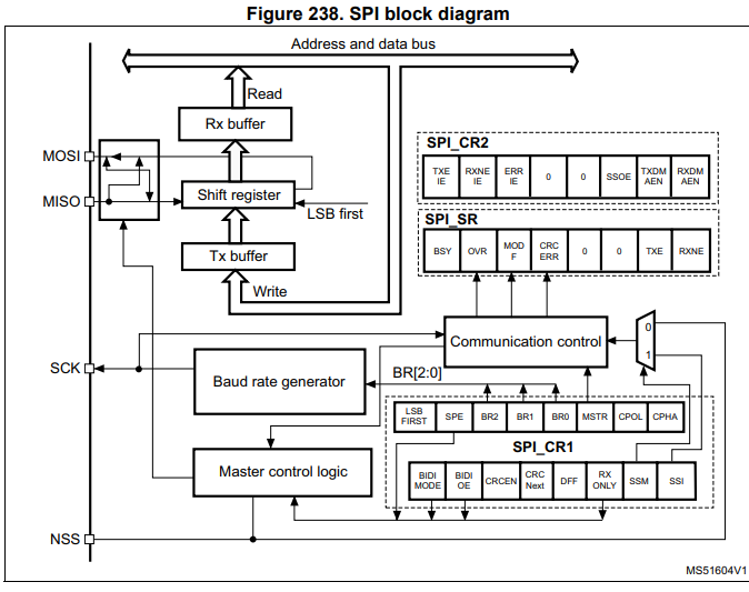
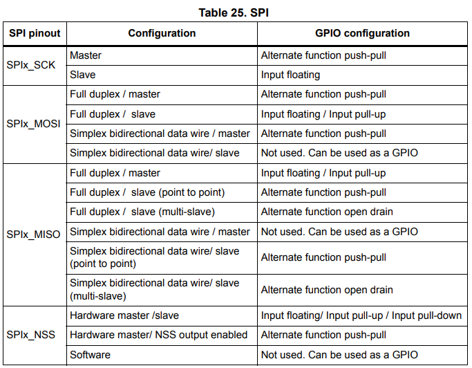
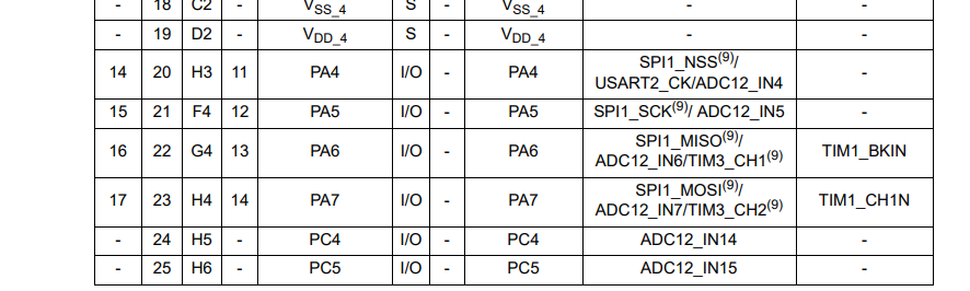

FIG 1- Selecting MOSI, MISO , SS and SCK pins
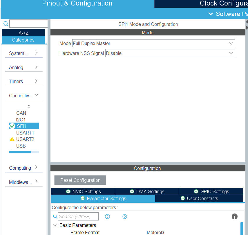 FIG2 – Selecting the operating mode
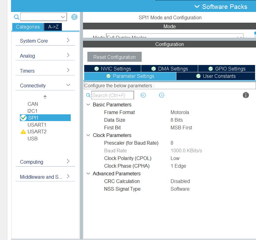
FIG3 – Configuring the parameters
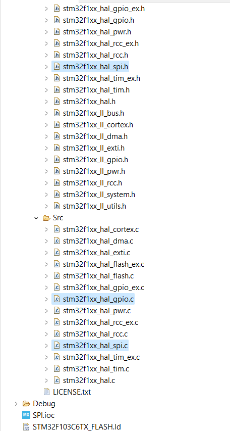
FUNCTION NAME
HAL_StatusTypeDef HAL_SPI_Init (SPI_HandleTypeDef * hspi)
FUNCTION DESCRIPTION
This function initializes the SPI peripheral according to the parameters and intialize the handle typedef
PARAMETERS
hspi: pointer to a SPI_HandleTypeDef structure that contains the configuration information for SPI module.
RETURN VALUES
HAL-STATUS
FOR EXAMPLE
FUNCTION NAME
void HAL_SPI_MspInit (SPI_HandleTypeDef * hspi)
FUNCTION DESCRIPTION
This function initializes the Msp of SPI
PARAMETERS
hspi: pointer to a SPI_HandleTypeDef structure that contains the configuration information for SPI module.
RETURN VALUES
NONE
FUNCTION NAME
HAL_StatusTypeDef HAL_SPI_Transmit (SPI_HandleTypeDef * hspi, uint8_t * pData, uint16_t Size, uint32_t Timeout)
FUNCTION DESCRIPTION
This function transmits certain amount of data in blocking mode
PARAMETERS
- hspi: pointer to a SPI_HandleTypeDef structure that contains the configuration information for SPI module.
- pData: pointer to data buffer
- Size: amount of data to be sent
- Timeout: Timeout duration
RETURN VALUES
HAL-STATUS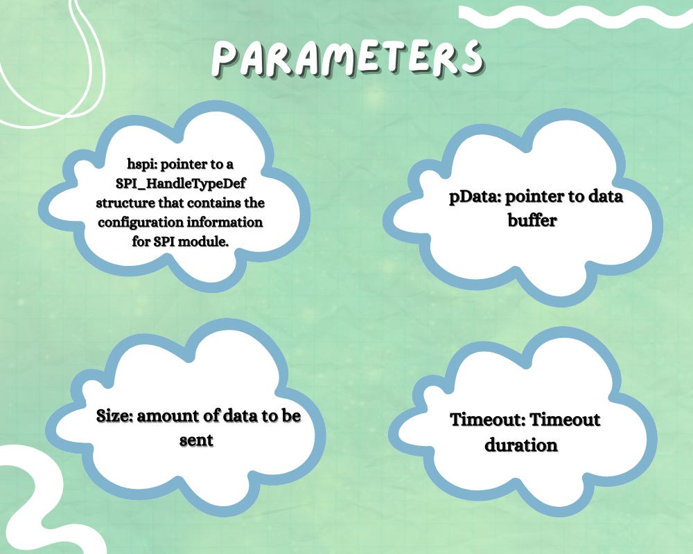
FUNCTION NAME
HAL_StatusTypeDef HAL_SPI_TransmitReceive (SPI_HandleTypeDef * hspi, uint8_t * pData, uint16_t Size, uint32_t Timeout)
FUNCTION DESCRIPTION
This function is used to both transmit as well receive certain amount of data in blocking mode
PARAMETERS
- hspi: pointer to a SPI_HandleTypeDef structure that contains the configuration information for SPI module.
- pTxData: pointer to transmission data buffer
- pRxData: pointer to reception data buffer
- Size: amount of data to be sent and received
- Timeout: Timeout duration
RETURN VALUES
HAL-STATUS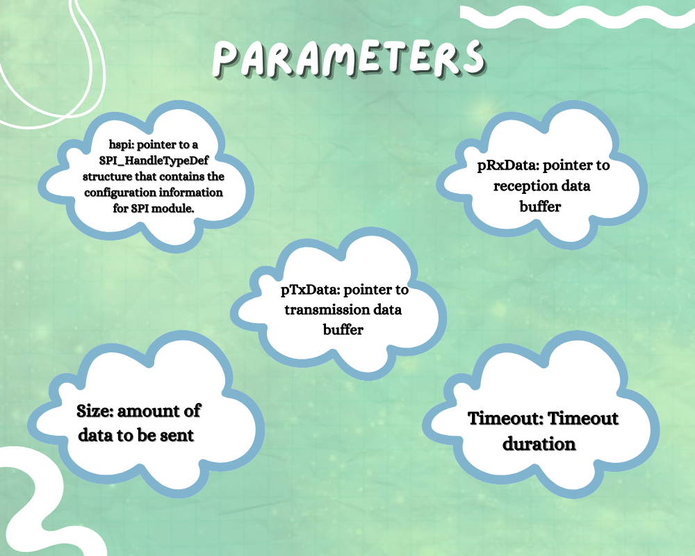
FUNCTION NAME
static void MX_SPI1_Init(void)
FUNCTION DESCRIPTION
This function is used to intialize the SPI1 along with the parameters
PARAMETERS
NONE
RETURN VALUES
NONE