
What is ADC Module of Autosar MCAL Module?
The ADC Module, or ADC driver, of the MCAL Layer, serves as the standard/stack for the Analog to Digital Peripheral of Automotive microcontrollers. Real-Time Drivers (RTD) are software stacks used to operate the peripherals of Microcontrollers. The Autosar MCAL layer is a global-level RTD stack designed for automotive MCUs. For more information on Autosar MCAL, please refer to our blog.
Understanding how the ADC Driver of the MCAL Layer operates, including its APIs, configurations, parameters, and the sequence of APIs needed to utilize different features of the ADC peripheral, is essential for utilizing the ADC peripheral of any automotive MCU using Autosar Technology. Similar to the Arduino IDE environment, where universal functions are used for various microcontrollers, the ADC Driver of Autosar MCAL Layer provides universal APIs and concepts for using the ADC peripheral with automotive MCUs such as NXP S32, Renesas RH850, Infineon TriCore, and others.
In addition to understanding the APIs, the use of MCAL GUI configurations is also necessary when working with the MCAL layer. These GUI configurations are typically done using Autosar Code configurator tools such as EBTresos or Vector. While these configurators offer multiple sections for customization, the configurations are largely universal across different automotive MCUs. Understanding these configurations is crucial for effectively utilizing the ADC MCAL layer.
To fully grasp these configurations and APIs, it is important to have a solid understanding of the functional concepts of the ADC Driver. These concepts will be further elaborated on in the following sections.
Autosar MCAL ADC Driver specs
- ADC Driver targets only ADC peripherals which run according to successive approximation techniques. Delta Sigma ADC technique is not supported and not recommended for use in automotive MCUs.
Autosar MCAL ADC Working concepts
Before getting to know how to use the ADC MCAL API’s, it is important to understand the functional concepts that are used and involved while using and configuring ADC Driver API’s in autosar MCAL.
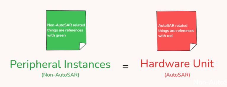
ADC Hardware Unit
- Each Instance of ADC peripheral of a microcontroller in the ADC Driver is termed as ADC Hardware Unit. So, if a microcontroller has 2 instances of ADC peripheral, then it will be said to have 2 ADC hardware units. If the microcontroller has 4 instances of ADC peripheral, then it will be said to have 4 ADC hardware units.
- Like S32K144 MCU has 2 instances of ADC. So when we configure, then one can see in the ADC hardware unit drop down there are 2 ADC hardware units. and say we are using S32K344 MCU, it has 6 ADC instances, so when we configure it has 6 ADC hardware units.
- The ADC Hardware unit will have the same number of ADC channels that are there in the corresponding ADC peripheral. Say if we have 16 channels in ADC instance 1 then the ADC hardware unit will also have 16 channels.
- Also, each ADC hardware unit will be denoted by an ADC logic Unit ID number. After the generation of configuration files that number is what is used in different ADC APIs to refer to the corresponding ADC hardware unit.
- And just like this, we configure the ADC clock, ADC prescaler values, ADC resolution, and ADC transfer type (Interrupt/DMA). All these things are there for each ADC hardware unit also.
Concept of ADC Groups and ADC Channels
- ADC channels are the ADC pins of the MCU, on which external analog sensors are connected.
- ADC Driver has the concept of ADC Groups and Channels. This means we can group the different ADC channels in a single group and then in Software, ADC conversion is done by referring to the whole group. All those operations are performed on all ADC channels of that ADC group.
- With that, there are some properties and
- It is mandatory to have at least one channel for an ADC group. ADC group with zero channels is invalid.
- In a single group, we can group 1 to ‘n’ number of channels. Here ‘n’ is equal to the total number of channels that are there in each ADC hardware unit.
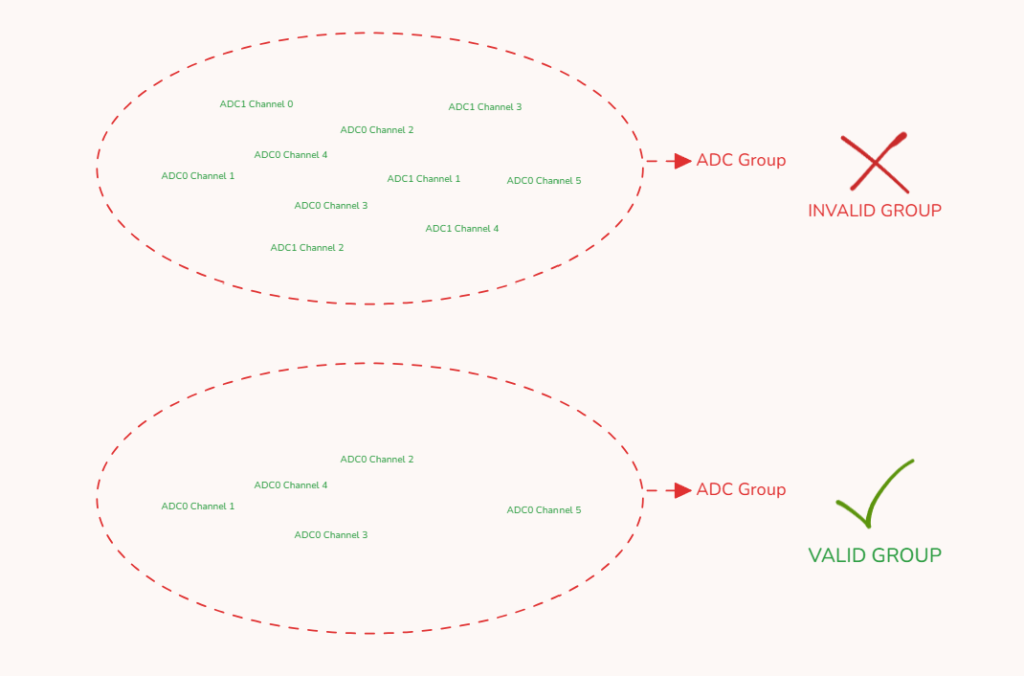
- The ADC channels that are grouped should belong to the same ADC hardware unit.
Analogy: Let’s say we have ADC1_Ch1, ADC1_Ch2, ADC0_Ch1, and ADC0_Ch2. Then we can’t group ADC1_CH1 and ADC0_CH1 in one group as these are of different ADC hardware units( instances). - The same ADC channel can be grouped in different groups but if an individual ADC channel is configured with limit checking values, then the group of that ADC channel will have only one ADC channel.
Analogy: Let’s say we have ADC0_CH1, ADC0_CH2, ADC0_CH3, and ADC0_CH4. CH1-3 are configured without any limit checks but CH4 is configured with limit checks. So we can have AD_Group1 with ADC0_CH1 and ADC0_CH2. AD_Group2 with ADC0_CH1 and ADC0_CH3. But we can’t group ADC0_CH4 with any of the above groups, for it new group AD_Group3 has to be formed in which only AD0_CH4 can be put in.
- Analogy: The reason for having the ADC configuration by the concept of ADC channel and group is that this enables us to group the ADC pins of the same application domain refereed by a single name while developing the software application. Say we have 3 analog hall sensors for the current measurement of BLDC winding. So can we configure 3 channels and group them in a single group by the name of BLDC_Hall. The virtue of this while developing embedded software applications it becomes easy for us.
ADC Group Notification and Priority
- The ADC driver of the Autosar MCAL layer gives the option of configuring and calling the notification callback when all of the channels of that ADC group have been converted.
- It’s like an IRQ handler. When the ADC transfer type is via Interrupts, then the ADC driver will invoke the ADC IRQ handler when ADC conversion of the ADC channel is done, the IRQ handler of the ADC driver stack is designed in a way that it calls the callback function of the ADC group. Thus, ADC group notification is enabled when we are doing ADC conversion via Interrupts.
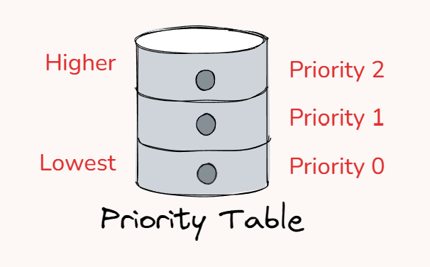
- ADC priority is a concept utilized when we are using multiple ADC groups with different channels in a single application. And we have to give higher weightage to readings of some ADC channels. So, we configure the higher priority to the ADC group, which has those higher weightage ADC channels.
- We can set the ADC priority in terms of software or hardware. ADC priority by software means that we assign a priority number to ADC groups, where 0 is the lowest priority and incremental numbers increase the priority. And ADC priority by hardware we mean, that we can assign priority numbers to ADC channels by some ADC peripheral registers.
- ADC_PRIORITY_HW denotes priority by hardware. ADC_PRIORITY_HW_SW denotes priority by both hardware and software. If hardware support is both their then only pure software priority mechanism is theirs.
- Aborting-restarting or suspend-resuming operations have to be done on low-priority ADC groups when higher-priority ADC groups are called. To do so ADC Driver implements the concept of queues to manage the information of ADC groups.
ADC Conversion Start /Trigger
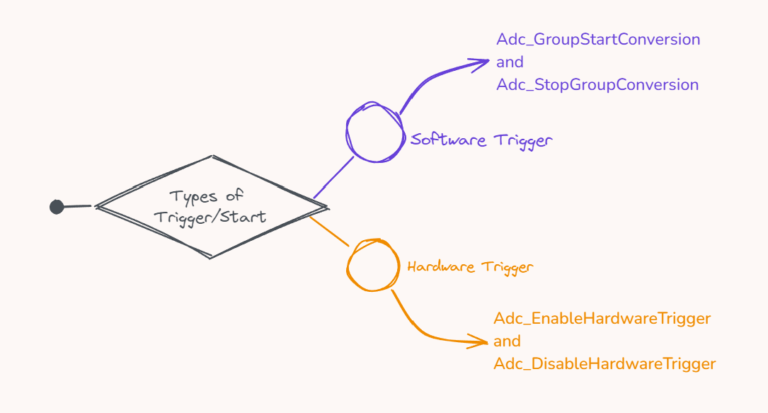
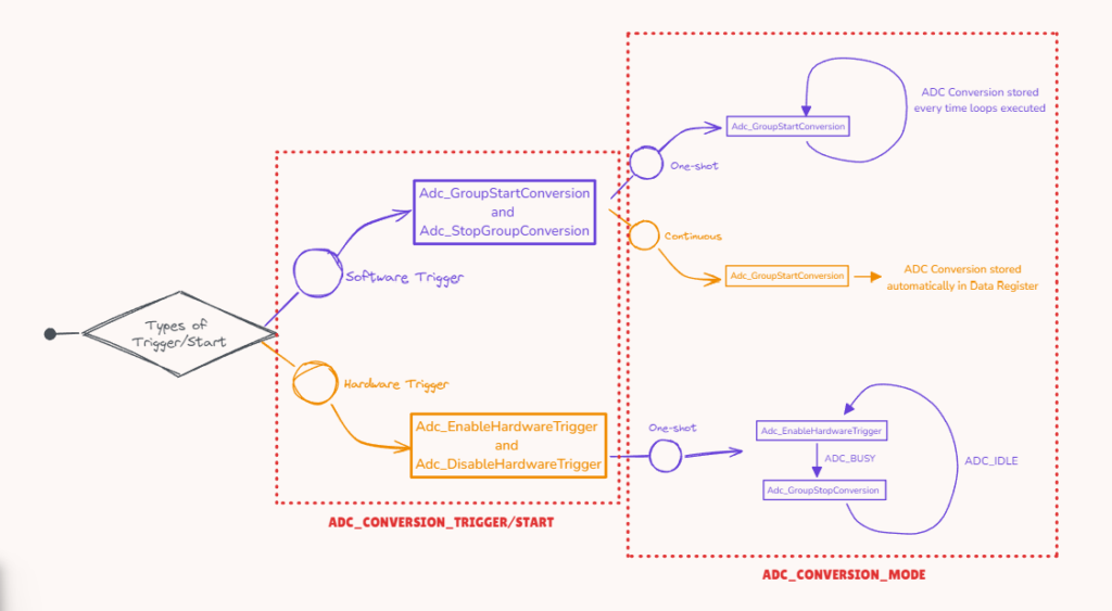
- ADC conversion trigger or conversion start refers to an event or signal that initiates the process of converting an analog input signal to a digital value. The main usage of an ADC peripheral is to convert the Analog value which is input to the MCU pin into a Digital value so that the microcontroller can understand the analog value. So when to start this conversion, depends on the ADC conversion method we have configured. It can be either Software Trigger or Hardware Trigger.
Analogy: Consider it like when to open the door of a house, depending on an event. Whether someone from outside has come, that will be called a hardware trigger or whether someone from inside the house had to go, that will be called a software trigger. - By software trigger, we mean that in main.c, or application we will give a software command (that will write some bits values to ADC peripheral registers of an MCU) which tells the ADC peripheral to start the ADC conversion. The APIs Adc_GroupStartConversion and Adc_StopGroupConversion are the APIs that will be used in embedded software applications for doing ADC conversion by software trigger.
- By hardware trigger, we mean that when some external signal is fed into MCU like a digital High or low signal on pins of MCU, PWM signal on pins of MCU, etc, that will start the ADC conversion. The APIs Adc_EnableHardwareTrigger and Adc_DisableHardwareTrigger are the APIs that will be used in embedded applications for doing ADC conversion by hardware trigger.
- We can configure the ADC conversion method for each group. And all the channels of that group would be converted with that ADC conversion method.
- One important thing here is that for Hardware Trigger conversion mode the configuration would be a bit different from MCU to MCU. But APIs used in software applications would be the same. For doing ADC conversion by hardware trigger there is the use of extra peripherals of the MCU, that help/support the ADC peripheral to trigger via external signals. Like in NXP S32K144 MCU, we have PDB and TRGMUX peripherals for doing ADC conversion by hardware trigger. In NXP S32K344, we have a BCTU peripheral for doing ADC conversion by hardware trigger. So, if we have configured ADC conversion mode by hardware trigger, the configuration of these peripherals is also done along with it.
ADC Conversion Mode
Another important concept is of ADC conversion mode. By conversion mode, we mean whether ADC conversion will keep on happening continuously or only once after ADC conversion has been started.
The ADC Driver of Autosar MCAL layer has 2 types of ADC conversion modes: One-Shot conversion mode or Continuous conversion mode.
In the case of One-Shot conversion mode, After every Conversion, we have to give a trigger signal again to get the new ADC reading. Whereas in the case of Continuous conversion mode, once the trigger signal is given, ADC conversions will keep on happening again and again.
One-shot conversion mode is supported for both the types of ADC Trigger: Software and Hardware trigger. In the case of Software Trigger, Adc_GroupStartConversion starts the ADC conversion, so we have to call this API again and again to do the ADC conversion. In the case of Hardware Trigger, Adc_EnableHardwareTrigger starts the ADC conversion, so we have to call this API again and again to do the ADC conversion. When ADC conversion is started, the group status of ADC is set as ADC_BUSY. By calling the API’s Adc_StopGroupConversion and Adc_DisableHardwareTrigger the group status of ADC is set to ADC_IDLE mode. Before calling the new one-shot conversion trigger signal, make sure the ADC group status is set to IDLE mode.
Continuous conversion mode is supported only for ADC Software Trigger conversion. Continuous conversion mode of operation can’t be performed for ADC hardware trigger conversion. Started ADC continuous conversion can be stopped by ADC_DisableHardwareTrigger API in the software application.
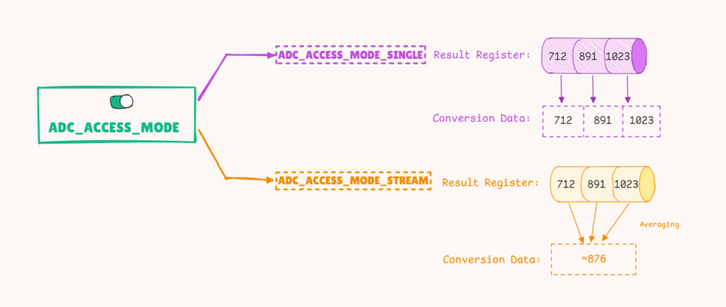
ADC Access Mode
- ADC Driver of Autosar MCAL layer provides the feature of ADC Access mode, meaning how many samples of ADC readings should be sampled for each channel of the group.
- ADC is a sampling of analog values and converting them into digital values. The more samples we do, the more accurate the readings take up more time. We can configure whether the ADC readings have to be sampled only once or ADC readings have to be sampled in a stream.
- ADC_ACCESS_MODE_SINGLE and ADC_ACCESS_MODE_STREAMING are 2 access modes for ADC. We can configure the types of access modes for both ADC conversion modes(One-Shot and Continuous) and ADC conversion triggers.
- In Streaming access mode, we configure a number of ADC samples that should be taken in a single stream after a trigger event for each channel of a group. Say we have a group with 2 channels and the number of samples of the ADC group has to be taken is 4. So in total group will store 8 readings. 4 samples of each channel.
- In Single access mode, only 1 ADC sample of each channel of a group is taken. So group with 2 channels will store 2 readings, 1 reading for each channel.
ADC Driver Specs
In ADC driver of the Autosar MCAL layer, lists the features and specs of the ADC peripheral. However, not all the features of the ADC driver do not have to be there in all MCUs.
Take it like an ADC driver is a standard that lists specs and features for the ADC stack of the ADC peripherals of MCU. Now depending on features present on ADC peripherals of MCU, ADC driver would be supporting corresponding API’s and configurations. Now depending on MCU to MCU certain features and specs of ADC driver would be their and would be not.
General Specs of ADC driver:
- ADC channels or pins are referred to by grouping them in a single group.
- Each ADC group should have at least 1 ADC channel.
- ADC Conversion start: Software Trigger and Hardware Trigger
- ADC group prioritization by hardware and software.
- ADC group replacement on ADC priority: Abort-Restart or Suspend-resume
- ADC channel sampling mode via Liner and circular access mode.
- ADC hardware triggers signal types and trigger timings.
- ADC power states
- ADC channel limit checks
- ADC transfer type by interrupts and DMA.
- ADC conversion modes: One Shot and Continous mode
- ADC calibration, clock selection, and prescaler settings
Things we will be covering
Now we are going to use the S32K144 Microcontroller present on ElecronicsV3 development board for learning and doing the handson with ADC driver of MCAL layer. S32K144.
ADC driver for S32K144 would be having all the above points apart from 7 and 8th point. And Of 5th point only abort-restart group replacement on ADC priority is supported.
In the basic course, we will be covering follwoing features and points of ADC driver:
- ADC notification callbacks via Interrupts
- ADC One Shot conversion mode by hardware and software trigger.
- ADC grouping of multiple channels and single channel in different ADC groups.
- ADC calibration , clock setting and prescaler settings
- ADC single mode access mode.
And in the end, we will be making basic DIY projects using these features via Autosar MCAL ADC driver on ElecroncisV3 board: