Index/Blueprint
- What are TIMER peripheral in MCU?
- Concepts involved in Timer peripheral?
- Types of Features in TIMER peripheral in MCU?
What is TIMER Peripheral in Microcontroller?
- A timer peripheral in a microcontroller is a peripheral that is used to count the clock cycles in the form of ticks to generate/ capture different forms of digital signals and to generate time delay. ( For now we will not focus on time delays)
Here by digital signals, we mean the PWM signals. PWM signals are raw digital signals having the rapid switching from High to Low state. So, using TIMER peripheral we can generate and capture these PWM signals.
(In a Microcontroller, clock signals are a type of signal that oscillates btw a high and low state and in that each pulse is a tick)
When used for generation of PWM signals, its objective is to control the voltage/current across a device by manipulating its frequency and duty cycle parameters.
- In which frequency determines how fast the signal switches from High to Low state and Low to high state. Higher the frequency, higher is the switching rate. Means faster the device will get On and Off. On at High Time and Off at Low time. This frequency is so fast that, device doesnt gets off, but it gets some mean/average volatge across itself because of multiple high and low signals within very short time. This short time is basically frequency. Say if we say frequency of 100 hertz, meaning in 1 sec signal will be switching state ,100 times. If we say frequency of 10,000 hertz, meaning in 1 sec signal would be switching at 10,000 times.
- And duty cycle determines, how long the signal would be in high state and how long the signal would be low state. Higher is the duty cycle, means higher is the High time of PWM signal. So, more voltage would be provided to end device. Lower the duty cycle, means lower is the High time of PWM signal. So, less voltage would be provided to end device.
When used for capture of PWM signals, its objective to decode the external digital data by calculating its Frequency and Duty cycle values.
- Based on these values, of external PWM signal, MCU can get to know what the readings of number of external sensors. Several sensor circuits generate PWM (Pulse Width Modulation) signals directly, as PWM is a convenient way to encode sensor outputs into a digital format.
- Sensor outputs like: Temperature sensor, light sensor, current sensors, ultrasonic distance sensors, pressure sensors and list is very large.
Functional Concept in Timer Peripheral
- TIMER Counters:
- Types of Counters
- Running Counter
- MAX Counter
- Compare/Capture counter
- Types of modes in which counter runs
- Up-counting
- Up-down counting
- Types of Counters
> Counter Register
–> There are basically 3 references that help in tracking in Counters:
- Initial Value Variable (INT): Let’s refer this variable as INT. Now, this variable gives the reference to counter that from the counting will begin.
- Moving Value Variable (MOV): We’ll be referencing this variable as MOV. This variable moves to-and-fro between INT AND MAX variable performing the actual counting.
- Final Value Variable (MAX): Finally, this variable will be referenced as MAX. This variable sets the end point of the counter.

> TIMER Counter
Now in TIMER peripheral, to generate and capture these PWM signals there are concepts of Counters in it. Counters as its name says, count the mathematics numeric numbers. There are 3 types of Counters:
- Running counter: This counter is free-running and keeps on running either in incremental or decremental order.
- MAX counter: This counter has the value up to which value, the running counter runs.
- Compare/Capture counter: This counter stores the value, according to which state of the PWM signal changes from High to Low or Low to High. ( It should be of less value than the MAX counter value)
So how things work is, as we start the Timer peripheral, the running counter starts counting from 0 value to the value stored in the MAX counter. And now depending on whether we want to generate or capture, the compare/capture register role will come in.
> Types of Counting performed by Counters
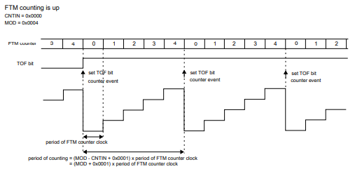
–> Up Counting: In Up Counting mode for the FlexTimer Module (FTM), the counter starts from the value specified in INT and increments until it reaches MAX. Once it hits MAX, the counter resets back to INT and continues counting.
![]()
Additionally, the TOF (Timer Overflow Flag) is set when the counter transitions from MAX back to INT. This mode is commonly used for edge-aligned PWM or simple counting operations.
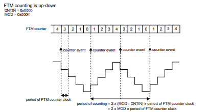
–> Up-Down Counting: In up-down counting mode for the FlexTimer Module (FTM), the counter starts from the value specified in INT, increments to MAX, then decrements back to INT, and repeats this cycle.
![]()
The TOF (Timer Overflow Flag) is set when the counter transitions from MAX to one less than MAX (MAX – 1). This mode is typically used for center-aligned PWM generation.
> Timer Clock and Prescalar
–> The FTM Input Clock is not an independent clock in the MCU. It is connected through MCU’s main clock option and then it runs on the very same frequency.
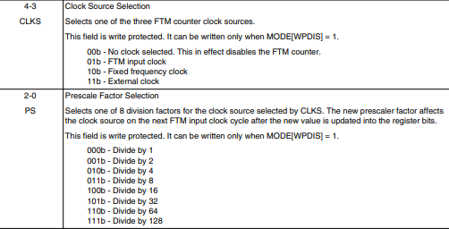
–> But we can always customize the clock period of the FTM peripheral by choosing a different clock and prescalar. Prescalar is a specific value that divides the clock into desired frequencies.
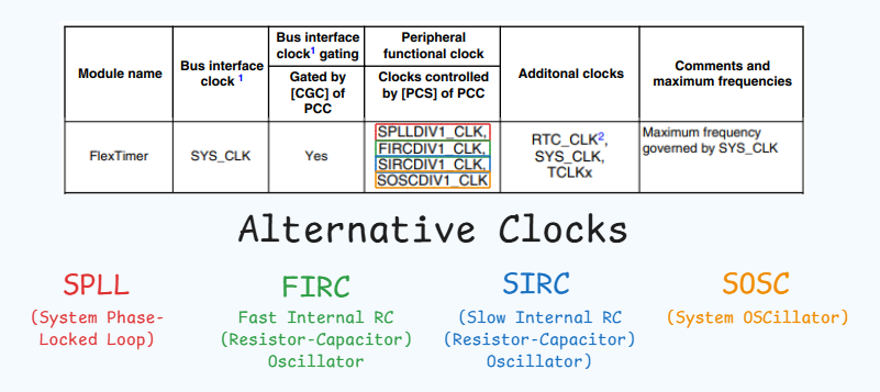
–> Above you can also see a column named “Additional Clock” where we can also use external clocks and fixed frequency clocks.
–> Below is the mentioned SC register where the FTM clock and prescalar configuration can be seen:
Types of features in TIMER Peripheral in MCU
- Time Delays
- Output capture mode: PWM signals
- Input Capture mode: capturing external PWM Signals
Time Delays
Time delay feature is feature in which we do not output or input any PWM signal. We just use counters for generating delays. Till the time running counter reaches MAX counter value delays are generated.
Output Capture feature: PWM Signals
As its name says, the Output Capture feature outputs the digital signal. In the output capture register, the PWM signals are outputted via the Microcontroller pin. In this, there is a concept of PWM signal state and edges. That is which PWM signal state should be outputted first: High signal or Low signal. And which PWM signal state should be outputted after the Compare match. Based on this value polarity of PWM signals is determined. If we have configured to output a High signal at first, then after comparing LOW signal should be configured. If we configure a High signal only, then no PWM signal change we will see.
Working of PWM signals
If we want to generate, then the value would be stored in compare register by MCU and as the running counter starts incrementing from 0 value, the digital signal generated from the MCU pin would be of High state or Low state( that we can configure in programming which state of the signal should be generated at first) and
- as the Running counter reaches to Compare register value, the PWM signal state toggles from the previous state, (that is state of the pin changes from High signal (if that is the previous state) to low signal or low signal (if that is the previous state) to high signal).
- And for time till the running counter reaches the max counter value, that new state signal is generated, and as the Running counter reaches to MAX counter value, the PWM signal state toggles again to the original state.
- And then this process keeps on happening to generate the PWM signal.
So you will see that the compare register value determines the duty cycle, for how long the signal should be kept high or how long the signal should be kept low. The value of the MAX register determines the frequency, as according to the MAX register value the same pulse would repeat, so the less the MAX register value more pulses would be the greater the frequency would be there.
Based on the nature of PWM signals there are 3 types of PWM signals in an MCU
> Types of PWM Signals:
- Center Aligned: The signal’s duty cycle is symmetric around the center of the period. The counter increments and then decrements, creating a triangular waveform. Ideal for reducing harmonics.
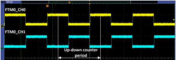
- Edge Aligned: The pulse starts at the beginning (or end) of the period and ends when the duty cycle is reached. The counter either increments or decrements. Commonly used for simplicity.

- Complementary: Two signals are generated with opposite phases (when one is high, the other is low). Used in motor control and power converters to drive half-bridge or full-bridge circuits.

Input Capture Modes: External PWM signals
In the case of the ICU signal, we collect the external digital signals. For that, we need to configure which state of the external PWM signal should be detected first and what states of the external signal should be captured. Based on that signal measurement happens.
> Working of ICU signals:
If we want to capture, then we first configure which state of external signal we want to capture: High state (Rising edge) or Low state (falling edge). Based on the state captured on the Pin of MCU, the value of the running counter is shifted to the Capture register. And then using these values in the capture register PWM parameters are calculated.
- For a better understanding of it, the running counter would start incrementing from 0.
- Now let’s say we have configured both states (High State and Low state) of the PWM signal to be captured. So, when the first High signal comes in, the running counter has a value of 1000, so the Capture registers get a 1000 value,
- after that low state comes in and at that point running counter has a value of 2000, so the capture register gets a 2000 value.
- And subtraction of this 2000-1000 value would be the Duty cycle. As this is the amount of time signal is High.
- After that again High signal would come and in the capture register, we get a 3000 value. So, 3000-1000 would be the period of the PWM signal, from which we can calculate the frequency of the PWM signal.
And so and so for. We just have to take care that the MAX counter value is not capped. That is if the external PWM signal is of very low frequency, then its period would be high and it should be not that high that the MAX counter value capes out.
> ICU Signal Parameters:
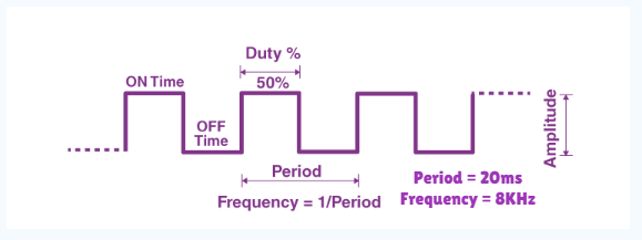
Signal Frequency: The number of signal cycles per second, measured in Hertz (Hz).
Duty Cycle: The percentage of the signal period during which the signal is high (active).
Edge Detection: Detects the rising, falling, or both edges of a signal to capture timing events.
Period: The time taken for one complete signal cycle.
Pulse Width: The duration of the high (active) state within a signal cycle.
TIMER Peripheral in Microcontroller
- Timer Instances and Timer Pins
- TIMER Counter value: 8 bit, 16 bit or 32 bit
Now in a Microcontroller to use TIMER peripheral, there are instances of TIMER peripheral. And each instance has some Microcontroller pins asscoitaed with them. Which can be used in TIMER peripheral mode to generate and capture such digital signals. In Timer peripheral we refer these pins as Channels. So Each Instance of TIMER peripheral has channels associated with it through which PWM signals can be captured and generated.
And the counters in TIMER peripheral can vary from 8 bit size to 32 size in MCU to MCU. Low end MCU’s like AVR Atmega 328 has 8 bit and 16 bit Timer counters. High end MCU’s like S32K144 has 32 bit Timer counters.
More the Timer counter value, means higher amount of PWM frequencies we can capture and generate.
