
What is PWM?
PWM or Pulse Width Modulation, is a type of digital electrical signal which is periodic in nature, with a rectangular waveform. There are certain terms associated with PWM which we need to understand before we move ahead. Here’s a graphical representation of a PWM signal-

· ‘Period’ = Tp , is the time it takes to repeat the same waveform
· ‘Duty cycle’ is the time for which the signal is a logic 1 by the total time period. Ton is the time for which the pulse is high
Hence, Duty cycle % = (Ton/ Tp) X 100

· ‘Frequency’ = F is the number of times the waveform repeats in a second. So, F = 1/Tp.
Applications of PWM signals
PWM signals have an extremely wide range of applications, here are a few of them-
· Variable voltage generator– if you vary the duty cycle of a PWM signal and apply it to certain electrical components, the components act as if they are receiving analog signals. This is because the response time of the components is finite. So, components like LEDs, buzzers, brushed DC motors etc. can be controlled by PWM signals. Meaning, you could control speed of a motor, brightness of an LED or amplitude of a buzzer and so on.
The voltage that they receive has a linear relationship with the duty cycle. So, if logic 1 is 5 Volts
0% duty cycle – 0V
25% duty cycle – 1.25 V
50% duty cycle – 2.5 V
75% duty cycle – 3.75V
100% duty cycle – 5V
· As a control signal – Some electrical devices/components analyze PWM signals that they are receiving to give a corresponding output. So, changes in the duty cycle are reflected in the output. These include Servo motors, electronic speed controllers (ESCs) and many more.
Here, the devices respond only to specific PWM duty cycles and frequencies
If you take the example of servo motors, they can only be operated at 50Hz signal with a duty cycle of 2.5 % to 12% . Anything beyond that doesn’t result in the movement of the servo. (The frequency and duty cycles vary from among different servos, this is a very common value which most 180-degree servos respond to)
Similarly, ESCs respond to a PWM signal with ON time of 1ms for minimum throttle and 2ms for maximum throttle with PWM frequency of 50 Hz. Some devices such as HCSR04 ultrasonic sensors give an output as a PWM signal in which the pulse width corresponds to the time it took for the ultrasonic wave to be received.
How is PWM signal Generated on STM32?? Timer peripheral
STM32 blue pill has 15 pins which can generate a PWM signal, with other models having even more pins for PWM generation. In this section, we will try to understand how PWM signals are generated by STM32
Every microcontroller has a built-in circuit which can measure the passing of time.
These are called Timers. What timers essentially do is count up to a certain
number and upon reaching that number, they change the value of a certain
register to indicate that the timer has counted up to that number.
Now, the time it takes to increment this count by 1 is determined by the timer’s clock
frequency. So, if the frequency of a timer is 1KHz, its time period will be 1
Millisecond. Hence, if we count up to 10, we have measured the passing of 10
Milliseconds. This is how, by simply incrementing a number, timers can measure
the time that has passed since the timer began counting. (This is how the
HAL_Delay() function generates delays)
The maximum
count a timer can make is determined by its register size. So, an 8 bit timer can
count up to 28 = 256,
10-bit timer –210 = 1024
16-bit timer –216 = 65536
32-bit timer –232 = 4294967296
So, a 1 bit increase in timer size equals
to double the count
Timers are extremely necessary for the functioning of a microcontroller as a lot of events in programs are time based, which you may not even realize.
Timer Peripheral modes and features
Coming to STM32 Blue pill, it has 4 timers of 16-bit size. To perform these functions, they need to be in specific modes. Here are all the modes in which timers can operate in STM32-
1. Input capture mode– In this mode, a pin on the board is set as input on which a PWM signal is sent by some device and we measure the frequency and duty cycle of that signal. This can be used to interface with devices such as HCSR04 ultrasonic sensors, which send a PWM signal as input to the microcontroller, where different parameters of PWM signals can be used to determine the distance which the sensor is trying to measure.
2. Output compare mode– In this mode, the timer is used as a counter and the count is compared to a register which contains a pre-programmed value, when they are equal, a software interrupt is generated and using this, a given pin is switched high or low. This mode comes in very handy when you are making a project which requires you to use multiple peripherals and at the same time generate a rectangular waveform of a given frequency and duty cycle, as it is interrupt based.
3. One pulse mode– In this mode, a pulse can be generated based upon a trigger from an input pin on the board , the pulse generation takes place after a certain delay from when the input trigger pulse was detected. This can be considered as a combination of mode 1&2 (IC &OC)
4. PWM generation mode– In this mode, we can generate a PWM signal on a given pin by fixing a frequency and a duty cycle. This is the mode we will be using to generate PWM signals through the main loop. The difference of this mode to mode 2 (Output compare mode) is that PWM generation mode doesn’t use interrupts to generate a signal and with output compare mode you can also generate a signal different than a PWM signal. This mode is generally used just to generate PWM signals and nothing more.
We encourage you to read about these modes in the documentation provided by STMicroelectronics to understand everything in a detailed manner –
Go to section 14 “Advance control timers” and section 15 “General purpose timers”. It is good practice to read through reference manuals to understand details and nuances
Timer peripheral in STM32 Blue Pill
The Blue Pill has a total of 4 timers. They are sub-divided into Advance timers and General-purpose timers.
Advance timers | General Purpose timers |
TIM1 is the advance timer present on the STM32 blue pill. Its clock frequency input is independent of other timers |
TIM2-TIM4 are general purpose timers on STM32 Blue pill. Their clock frequency input is independent of TIM1 |
They support all 4 modes, and also provide features such as complementary outputs of the generated signal and Repetition counter to update the timer registers only after a given number of cycles of the counter. |
They support all 4 modes, but do not provide features such as complementary outputs or repetition counters. |
Now, we need to first understand how are we going to set the base frequency for our timers, for this we need to look into the clock tree provided in the reference manual-
go to section 7.2 ” Low-, medium-, high- and XL-density reset and clock
control (RCC)” to find the clock tree.
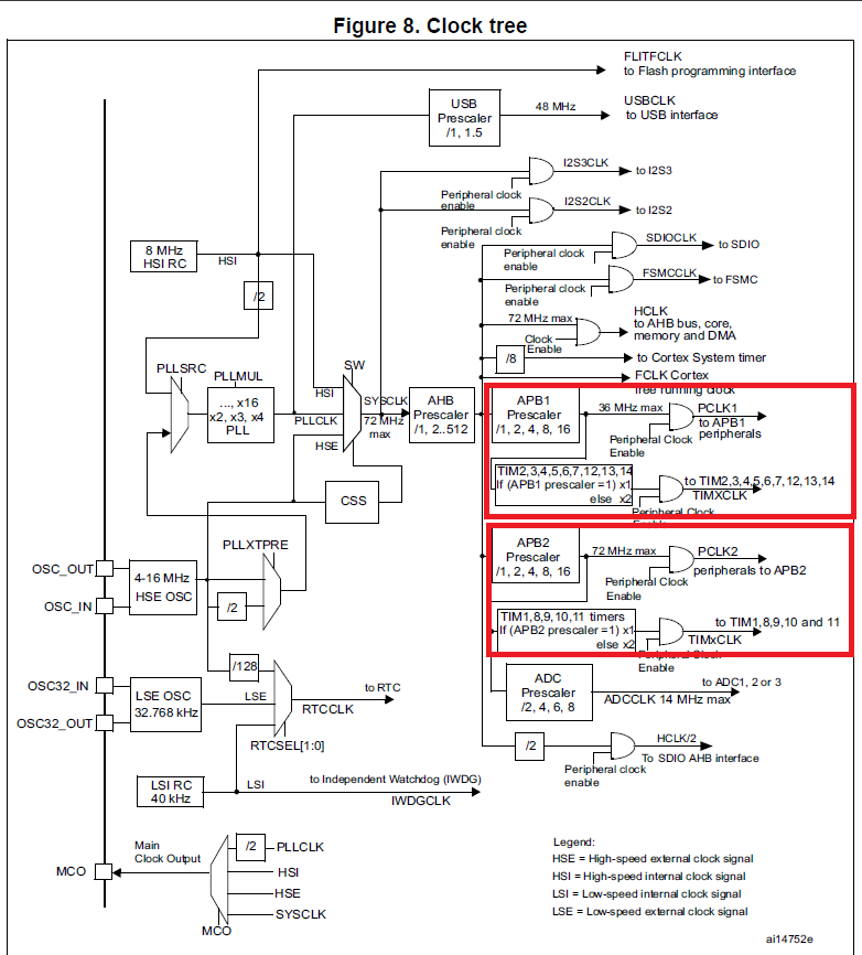
Since the reference manual is common for
STM32F103xx, STM32F101xx, STM32F102xx and STM32F105xx series, you will see up
to 14 timers, but we are concerned with only timers 1-4 , as those are the only
timers STM32 Blue pill has.
If you look closely in the clock tree, you will observe that the clock for TIM1 is connected to APB2 Prescaler and TIM2,3,4 are connected to APB1 Prescaler.
(APB stands for Advance Peripheral Bus. APB is a interconnect specification for the connection and management of functional blocks, i.e. internal circuitry for peripheral management)
To set the timer clock frequency for a given timer, follow these steps-
First, after you create the project file for this project, enable the HSE clock as shown here under the ‘pinout and configuration’

Now, under the ‘clock configuration’ set HCLK to 72 MHz .You can also see a few more important things here. The APB1 and APB2 Prescaler & APB1 and APB2 timer clocks

The APB1 Timer clock decides the frequency at which TIM2,3&4 will operate and similarly the APB2 Timer clock decides the frequency at which TIM1 will operate. This is the base frequency of the timer with which we will work.
PWM Signal generation with STM32 Blue pill
Now that we have understood how to do some basic setup of clock frequency of the timers, we are ready to generate PWM signals by setting up a few more things and writing some code.

· Go to the Pinout
and configuration menu and select TIM1.We will use timer 1 for implementing our
PWM signal generation.
· Then under clock source, Select ‘Internal clock’. This clock source is the ‘Timer clock’
discussed in the previous section. This sets up the base frequency of your
timer.
· Under channel 1, select “PWM generation CH1”.
· As soon as you do this, you will see pin PA8 as TIM1_CH1, meaning that our PWM output will be generated on this pin.

· Under configurations, set the Prescaler to 72-1. The Prescaler automatically adds 1 to the input value. So, if it the value entered was 0, the Prescaler = 1. (Note that the value is a 16-bit number, so you cannot exceed 65536)
· Prescaler decides the Timer Frequency. (Note that Timer Prescaler is different from APB1/2 Prescaler).
· Timer frequency = Timer peripheral clock frequency/ Prescaler
· So, in our case, Timer Frequency = 72MHz/ 72 = 1 Mhz.
· This is the frequency at which the timer will operate.
· Now we need to set our PWM frequency. PWM frequency = Timer Frequncy / ARR value
· ARR (auto reload register) decides the value at which the timer starts counting again. Set it to 10,000 as of now, you can set it as per your wish as well (This value is also a 16-bit number)
· Now PWM frequency = 1Mhz/10000 = 100Hz
· Also, enable the Auto Reload Preload
· Now you can hit Ctrl+S and generate the code for these configurations
To set a certain duty cycle for our PWM signal, we need to change the CCR register value. CCR (Capture compare register) compares the value at which the timer has reached while counting and using that , it triggers the pin LOW after the required value is reached. Since we are using TIM1, we will use CCR1 for controlling the duty cycle
Duty cycle % = (CCR value/ ARR value) x 100 ….(1)
Code-
Now that we know how duty cycle is caluclated, we can create a function to change the duty cycle.
Here, since CCR value = (Duty Cycle %) X (ARR value) /100 ….from (1)
CCR = (Duty Cycle %) X 10 …(since ARR = 10,000)
Our function will also use the same equation to vary the CCR value for the required Duty cycle.
The function we will create will be outside the int main () loop

In the function we are creating here, we will first take the duty cycle in % as function input. Using that we apply the equation CCR = (Duty Cycle %) X 10
To set the value of CCR1 to something, we write TIM1->CCR1 = int x;
The Arrow symbol is used to de-reference pointers and change the value of a member in a structure or union in C++. To dive deeper, read this article by GeeksforGeeks – https://www.geeksforgeeks.org/arrow-operator-in-c-c-with-examples/
Next we use a new Function HAL_TIM_PWM_Start(&htimX, TIM_CHANNEL_Y)
X = timer value , in our case we are using timer 1, so X = 1
Y = Channel Value, in our case we are using channel 1, so Y =1
This function starts to generate a PWM signal based on the timer clock, Prescaler, ARR value and CCR value we have set.
Now, we will increase the duty cycle of this PWM signal using a for loop and then observe it at our output where we will connect an LED
The circuit is quite simple, just attach an LED at pin PA8.

The loop runs for 100 iterations and duty cycle is set to the iteration number. So, the duty cycle goes from 0-100%. We also provide a small delay of 20 milliseconds, otherwise it will be almost impossible to see the change in brightness of our LED as we change the duty cycle.
All our programs are always uploaded on my Github repository, you can also find this program under “STM32_LED_brightness” branch –https://github.com/indterminatedude/STM32-Gettobyte-programs/branches
Once you have written the code and compiled it, flash it to your board and you should see an output like this –
If you followed the steps properly, congrats!! Now you can generate PWM signals on your STM32 board!!
We hope you found this article helpful and were able to learn about PWM signal implementation on STM32 Blue Pill
