
–> UART stands for Universal Asynchronous Receiver Transmitter.
- Universal: It works with any transmitter and receiver.
- Asynchronous: No clock signal is used for data communication.
- Receiver & Transmitter: Handles serial data transmission and reception.
–> The first thing that might come to mind is, “What does asynchronous mean?” and “How does it differ from synchronous communication?” In simple terms, asynchronous communication refers to data transfer where the sender and receiver do not share a common clock signal. Instead, they rely on specific signaling methods—such as start and stop bits in UART—to synchronize data transmission on a per-byte basis. On the other hand, synchronous communication requires a shared clock signal between the sender and receiver. This clock ensures that both devices are in perfect sync, allowing them to transfer data continuously without needing start and stop bits.
–> UART enables serial communication without a clock signal, making it simple and widely compatible. But you must be thinking “Why serial communication?” “Is there any parallel communication?” and “If yes, why it is not talked about?“
- Starting from talking about parallel communication. Below is the image of parallel communication:
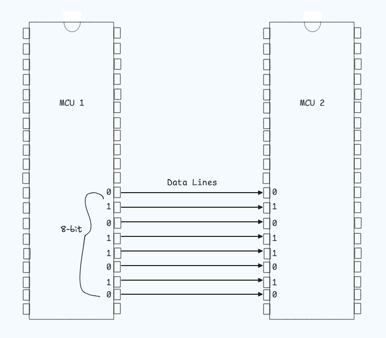
- This is how parallel communication looks for transferring 8-bit data. Does it look optimized to you? Obviously No. Cause here we can spot how the number of pins used is directly proportional to the size of the data which increases the bus complexity. But with these disadvantages, it also provides a great advantage which is faster data transfers. It’s a kind of trade-off between Serial and Parallel Communication for transfer speed v/s bus complexity.
–> Imagine two friends using walkie-talkies—they take turns speaking and listening, similar to half-duplex communication, where data flows in both directions but only one at a time. In contrast, a phone call allows both to talk and listen simultaneously, representing full-duplex communication, where data flows in both directions at the same time. Lastly, a radio broadcast, where one speaks and others only listen, illustrates simplex communication, with data flowing in one direction. UART typically operates in full-duplex mode, using separate TX and RX lines for simultaneous data transmission and reception, though it can also support half-duplex for certain scenarios.
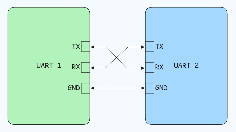
–>It uses two wires:
- TX (Transmitter): Sends data.
- RX (Receiver): Receives data.
–> Below you can see the connection of UART:
–> After learning the connection and basics of UART, it’s time to move on to the message structure. Message structure is a technical way of understanding how a message is created in a communication protocol.
–> Each packet contains:
- 1 Start Bit: Signals of the transmission start by pulling the line from high to low.
- 5-9 Data Bits: Actual data (can be 5-8 bits with parity, 9 bits without).
- Optional Parity Bit: Used for error checking(Parity is also explained below for less clustering).
- 1 or 2 Stop Bits: Signals the end of the packet by pulling the line back high.
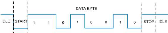
- The start bit is like the envelope.
- The data frame is the letter itself.
- The parity bit is a stamp that ensures the letter wasn’t tampered with.
- The stop bit is sealing the envelope.
Parity Bit in UART
–> The parity bit is an additional bit used in UART communication for error checking. It ensures the integrity of data by verifying if the transmitted bits match the expected count of 1s (either even or odd) in the data frame. Here’s how it works:
Purpose of the Parity Bit:
- It helps detect single-bit errors that may occur due to interference, noise, or mismatched baud rates during transmission.
- While it cannot correct errors, it signals the receiving UART to request a retransmission if an error is detected.
Types of Parity:
- Even Parity: The parity bit is set to 0 if the total number of 1s in the data frame is even. It ensures the overall count (data bits + parity bit) remains even.
- Odd Parity: The parity bit is set to 1 if the total number of 1s in the data frame is even. It ensures the overall count becomes odd.
Error Detection Example:
- Scenario:
- Data to be transmitted:
01100101(6 ones, even parity). - Parity bit added:
0(to maintain even parity). - Transmitted packet:
011001010.
- Data to be transmitted:
- At the Receiver:
- Data received:
011001011(error introduced in transmission, now 7 ones). - Parity mismatch detected (7 ones instead of 6 for even parity).
- Data received:
- Scenario:
Limitations:
- Parity can only detect errors caused by single-bit flips.
- It cannot detect multiple-bit errors or correct any errors.
UART is a protocol for serial communication, but it doesn’t define the electrical signaling standards. This is where standards like RS232(Recommended Standard 232), RS485(Recommended Standard 485), and TTL(Transistor-Transistor Logic) come in to define the voltage levels and physical connections used for communication.
- UART and TTL
- Link: UART outputs signals in TTL logic levels by default.
- High (1): Typically 3.3V or 5V.
- Low (0): 0V (ground).
- Use Case: Communication directly between microcontrollers, sensors, or modules that also use TTL levels.
- Key Note: TTL UART connections require compatible voltage levels; otherwise, level shifters are needed.
- Below you can see the hardware diagram of TTL.
- Link: UART outputs signals in TTL logic levels by default.

- UART and RS232
- Link: RS232 is a standard for serial communication, using different voltage levels:
- High (1): -12V (negative voltage).
- Low (0): +12V (positive voltage).
- Why Needed: TTL signals from UART are incompatible with RS232 voltage levels. A level shifter/translator IC (e.g., MAX232) is used to convert UART signals to RS232 and vice versa.
- Use Case: Communication with legacy devices like modems, industrial equipment, or PCs using serial ports.
- Link: RS232 is a standard for serial communication, using different voltage levels:

- UART and RS485
- Link: RS485 is a differential signaling standard designed for long-distance and multi-device communication over a single twisted pair.
- UART’s single-ended TTL signals are converted to differential RS485 signals using a transceiver IC (e.g., MAX485).
- Why Needed: RS485 supports robust communication over long distances (up to 1.2 km) and allows multiple devices (up to 32 nodes) to share the same bus.
- Use Case: Industrial networks, building automation (e.g., Modbus), and remote sensing.
- Link: RS485 is a differential signaling standard designed for long-distance and multi-device communication over a single twisted pair.
–> NOTE: Do not confuse yourself with RS232 or RS485 with VGA cable. These things are completely different things.