
Introduction
Remember that childhood day when we all loved to play with that remote-controlled toy car and many such toys. We were always curious to know how it works and what the rocket science behind this is. It was the microcontroller behind all those toys that control the entire operation. So Let’s dive deep and get ourselves clear on the basic concept of microcontrollers.
MCU: The Mastermind that Controls the Hardware

Microcontroller or MCU controls the hardware that implements the device operation. The MCU receives inputs from buttons, switches, sensors, and similar components; and controls the peripheral circuitry—such as motors and displays—by a preset program that tells it what to do and how to respond.
Here as shown in Fig.1, MCU consists of CPU (Central Processing Unit) that does the thinking, some Memory that stores relevant information, and some circuitry to implement Peripheral Functionalities (like a nervous system in the human body to receive inputs and give responses for outputs)
CPU: The Thinker
CPU is the control and operating unit of the MCU and hence is termed a thinker. The operating principle of the CPU is entirely determined by a program—an ordered sequence of instructions—stored in memory. The CPU simply reads and executes these instructions in a predetermined order.
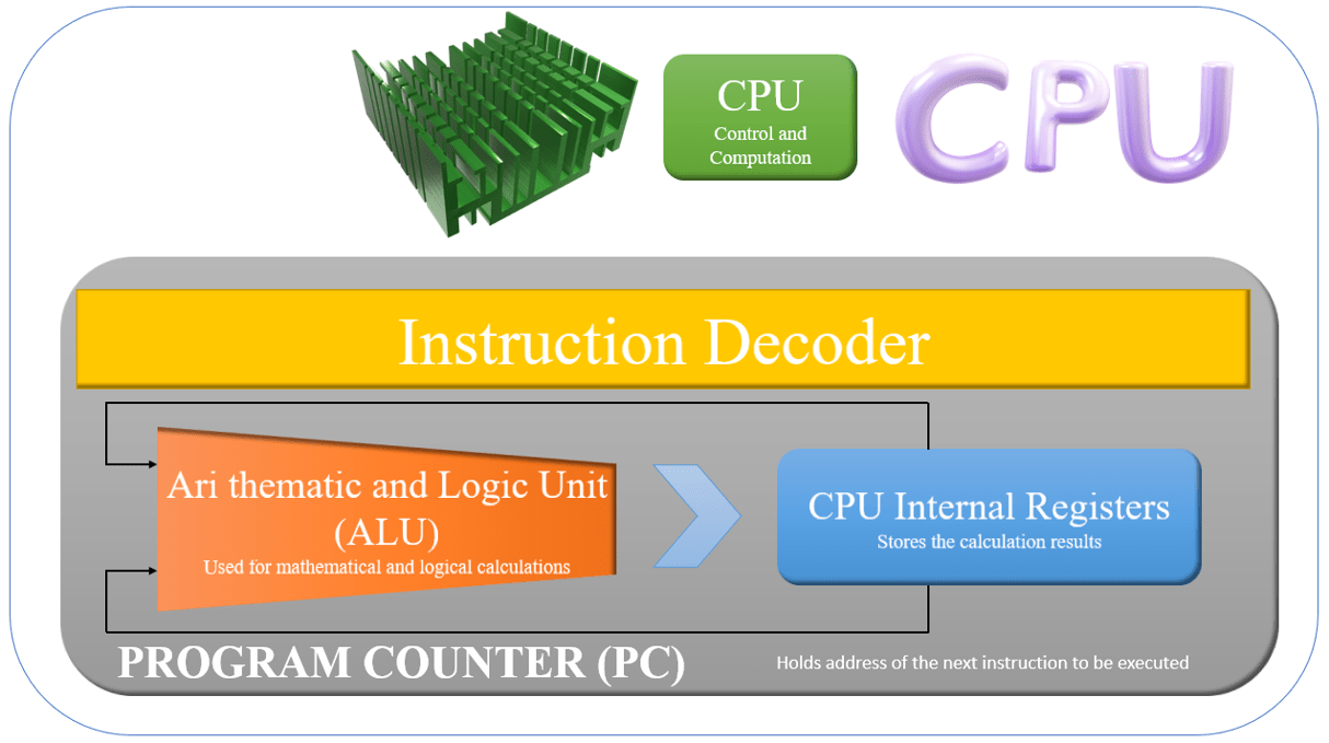
As we can see the structure of the CPU is divided into 4 parts:
- Program Counter (PC):
The PC is an internal register that stores the memory address of the next instruction for the CPU to execute. By default, the PC value is automatically incremented each time an instruction executes. It starts its Execution from 0000xH (Hexadecimal memory address) and gets incremented by 1 as the program executes.
- Instruction Decoder:
The decoder circuitry decodes each instruction, reads from the memory and uses the results to drive the MCU’s arithmetic and operational circuitry.
- Arithmetic and Logic Unit (ALU):
This circuitry carries out arithmetic and logical operations. Arithmetic operations include addition and multiplication; logic operations include AND, OR, and bit shifts. The ALU is controlled by the instruction decoder as shown inFig.2.
- CPU Internal Registers:
These registers store transient information. There are basically two types of registers in CPU, first is General-Purpose Registers, which holds the results of mathematical and logical operations, and the other is Specialized Registers that stores specific types of information—such as a flag register, which stores flag values (carry flag, etc.). For example, when the ALU performs an operation, the data is first copied at the specified memory address into a general-purpose register, and then ALU uses the register content for the calculation.
For Better understanding let’s have a look at an example. Here we are simply doing a mathematical calculation (addition) of 4 and 5.
| Memory Adrees in Hexadecimal | Instruction (a binary code value identifying the action to be taken) |
| 0000xH | Read 0010xH and Store Register A. |
| 0001xH | Read 0011xH and Store Register B. |
| 0002xH | Add Register B to Register A and Save in Register A. |
| Memory Adress | Data Before Execution | Data After Execution |
| 0010xH | 4 | 9 |
| 0011xH | 5 | 5 |
Now let’s see how this happen in CPU
STEP-1: As the CPU starts, it fetches the instruction stored at the address (0000xH) on the PC. It started decoding the instruction i.e to get the value from the user at 0010xH and store it in Register A.
STEP-2: After execution, The PC increments by 1 and moves to the next memory address (0001xH). It fetches the instruction, decodes it, and executes it, i.e., here to get the value from the user at 0011xH and store it in Register B.
STEP-3: Finally, after increment by 1, PC moves to memory address 0003xH where it fetches, decodes, and executes the instruction of adding the values of Register A and B and storing it in Register A, which holds the sum.
Memory: The Store
Memory in the microcontroller is used to store the program code and data. Broadly it can be classified into 2 types:
- Random Access Memory (RAM):
It is a volatile memory i.e.; it erases the content when the power cuts. It’s the fastest memory. RAM can be further divided into two categories:
- SRAM: Static RAM supports faster memory access and doesn’t require periodic refreshments. But due to complex circuitry making it difficult to design all the things in a single small size chip, hence only used in large memory sizes.
- DRAM: Dynamic RAM is a simple circuitry that can easily be mounted on a small size, although the size of DRAM is much bigger than SRAM. It is difficult to form DRAM together with high-speed logic on a single wafer. For this reason, it is typically connected to the chip and treated as peripheral circuitry.
- Read Only Memory (ROM):
It’s a non-volatile memory i.e., it remains in the memory even if there is a power cut. Since it’s read-only so we can only so we cannot erase any data or overwrite it. ROM is typically used to store the start-up program (executed immediately after power-on or reset), and to store constant values that may be freely accessed by running programs.
Peripheral Circuitry Control
So far, we understood the operation of general-purpose registers. Let’s see what exactly Special Function registers (SRF) do. They are basically used for controlling peripheral circuitry. In simple words, special function registers read the input data from the peripheral and write the corresponding output in the peripheral.
Let’s understand it with an example.
- The MCU composes 0 or 1 into a SFR spot to set the result to the peripheral to a LOW or HIGH level, which is associated with the SFR bit.
- The MCU peruses the worth of a SFR spot to get the status from the associated peripheral.
In Fig.3, pin A will be a broadly useful I/O line that interfaces with a particular piece (call it bit \”k\”) in one of the SFRs (refer to it SFR as \”j\”).
We should initially check out how the MCU utilizes the SFR spot to set the peripherals to one or the other HIGH or LOW levels.
- To set to LOW (0V), write 0 into bit k.
- To set to HIGH (5V), write 1 into bit k.


Then, see how the MCU utilizes the SFR spot to include the current status of the peripheral. Everything necessary is to peruse the bit value.
- In case the MCU peruses 0 from SFR-j bit-k, it realizes that the peripheral is contributing a LOW sign (0V) into Pin A.
- Assuming the MCU peruses 1 from SFR-j bit-k, it realizes that the peripheral is contributing a HIGH sign (5V) into Pin A.

In the same way, MCU can easily determine whether the external switch connected with it is ON or OFF by reading the SFR bit.
In a similar way, each MCU has lots of such SFR to interact with peripherals, read and write the data for the hassle-free execution of the MCU. Just imagine this analogous to the Human body and Nervous system, here MCU is like a human body and SFR is the nervous system, just like with our nervous we interact with the environment and can touch, feel, similarly with SRF MCU interacts with peripherals.
Conclusion
Let’s understand the importance of MCU’s. Why do we actually need them?
Imagine a simple circuit with wires, a switch, a 9V battery, and an LED. Do the necessary connection and we can see that the LED starts glowing when the switch is ON and stops when the switch is OFF.
Just imagine if we need to blink this LED at frequent intervals. Now we need to modify the circuit. It may be a complex circuit. We may require a timer IC to count the time intervals so that LED blinks at frequent intervals. But if we have an alternative to do both the tasks together i.e., to glow as well as blink LED at certain time intervals.
The MCU here plays an important role. If this LED is connected to an MCU, a person can do both the task without any further requirement and circuit.
Hence, the presence of the MCU makes it easier to switch between the operation and to add new functionality, which makes it clear, the importance of MCU.
Refrences
https://www.renesas.com/us/en/support/engineer-school.
