
Table of Contents
Why Was the CAN Protocol Introduced?
Let’s start from the basics: why did we need the CAN protocol in the first place? Imagine the electronics in a car before CAN was introduced. Each part of the car’s electronics had to be directly wired to every other part it needed to communicate with. This point-to-point wiring system had some big problems:
Too Many Wires: As cars got more advanced, they needed more electronic control units (ECUs) to handle all the new features. Each new feature meant adding more wires, making the system very complicated and heavy.
High Costs: More wires didn’t just mean more complexity; it also meant higher costs. Building and maintaining such a complicated wiring system was expensive, and finding and fixing problems in all those wires took a lot of time and money.
Hard to Expand: Want to add a new feature to the car? That meant even more wires and changes to the existing setup, which was a real headache. The system wasn’t built to easily handle new additions.
Interference Problems: With so many wires, there was a lot of electromagnetic interference (EMI). This interference could mess up the signals being sent through the wires, making the whole system less reliable.
Explaining the CAN Protocol
The Controller Area Network (CAN) is a robust protocol for connecting electronic control units (ECUs) in vehicles and other distributed systems. CAN was introduced to address the need for a more efficient, reliable, and flexible communication system in automotive applications. Let us explore how CAN works, starting with its fundamental layers.
The Physical Layer of CAN
The physical layer of CAN consists of a two-wire bus system called CAN_H (high) and CAN_L (low). Data is transmitted differentially, meaning the voltage difference between the two wires represents the actual data. This approach provides excellent resistance to noise and interference, ensuring reliable communication among all nodes on the network.
Data Link Layer in CAN
The data link layer is responsible for managing the data exchange between nodes on the CAN network. It consists of several key functions:
Framing: CAN frames consist of several fields, including the identifier, control, data, CRC, ACK, and end of frame. These fields structure the data and control information for transmission.
Addressing: Instead of traditional addresses, CAN uses message identifiers for addressing. Each message has a unique identifier that determines its priority and relevance to nodes on the network.
Error Detection: CAN employs multiple error detection mechanisms, such as the Cyclic Redundancy Check (CRC), acknowledgment checks, and form checks. If an error is detected, the erroneous message is discarded, and an error frame is transmitted.
Arbitration: When multiple nodes attempt to send messages simultaneously, CAN uses a non-destructive bitwise arbitration process. The message with the highest priority (lowest identifier value) wins the arbitration and continues transmission, while others wait for the next opportunity.
Importance of Synchronization
Synchronization is critical for the correct operation of the CAN network. To achieve this, all nodes synchronize their clocks at the start of each message transmission and continuously resynchronize throughout the message. This synchronization ensures that all nodes interpret the bit timings accurately and maintain a consistent understanding of the message.
- Hard synchronization occurs at the beginning of every message. When a node receives the start bit, which is indicated by a transition from recessive to dominant, it aligns its clock with that transition.
- Resynchronization happens throughout the entire message. As the message is being sent, nodes continually adjust their clocks based on the expected bit timings. If a node detects that a bit transition occurred earlier or later than expected, it adjusts its internal clock to stay in sync with the others.
Exploring the Versions of CAN Protocol
The Controller Area Network (CAN) protocol has evolved over time, leading to various versions, each offering enhancements over its predecessors. Here, we’ll overview the different CAN versions, with a primary focus on CAN 2.0.
Versions of the CAN Protocol
1. CAN 2.0A (Standard CAN)
- Identifier Length: 11 bits
- Message Size: Up to 2,048 unique message IDs
- Data Speed: Typically up to 1 Mbps
- Features: Standard data frames and error detection mechanism.
2. CAN 2.0B (Extended CAN)
- Identifier Length: 29 bits
- Message Size: Up to 536 million unique message IDs
- Data Speed: Typically up to 1 Mbps
- Features: Extended identifier field for more complex applications.
3. CAN FD (Flexible Data Rate)
- Enhanced Data Rate: Supports faster data transmission rates, up to 8 Mbps
- Data Length: Up to 64 bytes of data per frame
- Features: Flexible data rate and extended data field for more efficient communication.
4. CAN XL
- Higher Bandwidth: Supports even faster data rates, exceeding 10 Mbps.
- Extended Data Length: Capable of handling larger amounts of data
- Features: Improved protocol efficiency and higher performance for demanding applications
Focus on CAN 2.0
While all versions of CAN offer unique advantages, our primary focus will be on CAN 2.0, the foundation of the CAN protocol.
CAN 2.0A (Standard CAN)
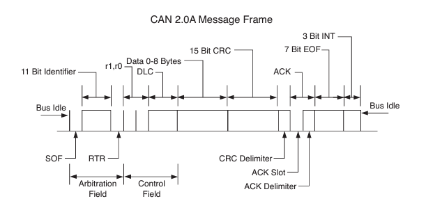
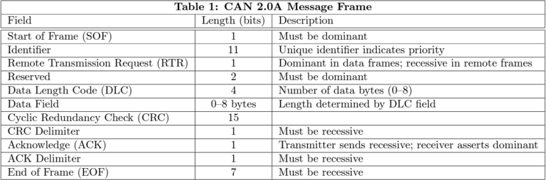
CAN 2.0A FRAME STRUCTURE OVERVIEW
1. Arbitration Field
The Arbitration Field is crucial for determining the priority of the message during arbitration:
- SOF(Start of Frame); 1 bit
- Determines the starting
- Identifier: 11 bits
- Uniquely identifies the message. Lower values have higher priority.
- RTR (Remote Transmission Request): 1 bit
- Indicates if the frame is a data frame (0) or a remote frame (1) requesting data.
2. Control Field
- Reserved bit: 2 bits
- DLC (Data Length Code): 4 bits
- Specifies the number of data bytes (0 to 8) in the Data Field. This allows the receiver to know how many bytes to expect.
3. Data Field
- Data Field: 0 to 8 bytes
- Contains the message content.
4. CRC Field
- CRC (Cyclic Redundancy Check): 15 bits
- For error checking of the Data Field.
- CRC Delimiter: 1 bit (recessive).
5. Acknowledgment Field
- ACK Slot: 1 bit (dominant if the frame is received correctly).
- ACK Delimiter: 1 bit (recessive).
6. End of Frame
- End of Frame: 7 bits (recessive).
7. Interframe Space
- Interframe Space: Variable recessive bits.
Interframe Space and Reserved Bits
- The Interframe Space is a short period of recessive bits between consecutive CAN frames. It allows the network to stabilize and prepares it for the next frame, ensuring smooth communication and avoiding collisions.
- Reserved bits (R1 and R2) in the CAN frame are included for future protocol enhancements. They do not carry any specific function in the current CAN 2.0 specification but are set to recessive values to ensure compatibility with future versions or extensions of the protocol.
CAN 2.0B (Extended CAN)
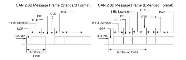
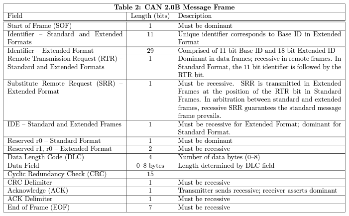
CAN 2.0B FRAME STRUCTURE OVERVIEW
1. Arbitration Field
- Identifier: 29 bits (Extended Identifier)
- Standard Frame (CAN 2.0A): 11 bits
- Extended Frame (CAN 2.0B): 29 bits
- RTR (Remote Transmission Request): 1 bit
- Indicates whether the frame is a data frame (dominant) or a remote frame (recessive).
- IDE (Identifier Extension): 1 bit
- Set to 1 for Extended Frames to indicate the use of the 29-bit identifier.
- Substitute Remote Frame: 1-bit
- Replaces the RTR bit in the Extended Frame, indicating whether the frame is a remote request.
2. Control Field
- DLC (Data Length Code): 4 bits
- Indicates the number of data bytes in the Data Field (0 to 8 bytes).
- R1 (Reserved): 1 bit
- A reserved bit for future use, typically set to a recessive value in practice.
- R2 (Reserved): 1 bit
- Another reserved bit is used similarly to R1.
3. Data Field
- Data Field: 0 to 8 bytes
- Contains the actual message data being transmitted.
4. CRC Field
- CRC (Cyclic Redundancy Check): 15 bits
- Used to detect errors in the Data Field.
- CRC Delimiter: 1 bit (recessive)
- Signals the end of the CRC.
5. Acknowledgment Field
- ACK Slot: 1 bit (dominant if the frame is received correctly)
- ACK Delimiter: 1 bit (recessive)
6. End of Frame
- End of Frame: 7 bits (recessive)
- Marks the end of the frame.
7. Interframe Space
- Interframe Space: Variable recessive bits
- Ensures a pause between frames for network stability.
Backward Compatibility
One of the notable features of CAN 2.0B is its backward compatibility with CAN 2.0A. CAN 2.0B can operate in Standard Frame mode (CAN 2.0A mode) by setting the IDE bit to 0. In this mode, the protocol behaves exactly like CAN 2.0A, using the 11-bit identifier format and ignoring the additional fields introduced for the Extended Frame format. This ensures that older CAN 2.0A devices can still communicate with newer CAN 2.0B devices without any issues, preserving compatibility across different versions of the CAN protocol.
By incorporating these enhancements, CAN 2.0B supports more complex systems and applications that require a larger number of unique identifiers and improved communication flexibility while maintaining interoperability with existing CAN 2.0A systems.
Key Differences Between CAN 2.0A and CAN 2.0B
- Extended Identifier: CAN 2.0B allows for a 29-bit identifier compared to the 11-bit identifier in CAN 2.0A, providing a larger address space.
- IDE Bit: In CAN 2.0B, the IDE bit is set to 1 to signal the use of the extended identifier.
- Additional Reserved Bits: R1 and R2 are reserved bits included in the Extended Frame format for potential future use.
Error Detection Mechanism in CAN
Error detection is crucial in ensuring reliable communication in CAN networks. CAN employs several mechanisms to detect errors, which can be bifurcated into two main categories: bit-level and message-level error detection.
Bit-Level Error Detection
1. Bit Monitoring
- In CAN, each node monitors the bus while it transmits data. If a node sends a bit but detects a different bit level on the bus (due to a collision or error), it flags a bit error. This ensures that discrepancies between transmitted and observed bits are quickly identified.
2. Bit Stuffing
- To maintain synchronization and detect errors, CAN uses bit stuffing. After five consecutive bits of the same polarity (either five dominant or five recessive bits), a bit of the opposite polarity is inserted. This prevents long sequences of identical bits, which could cause synchronization loss. If a receiving node detects more than five consecutive bits of the same polarity, it flags a stuffing error.
Message-Level Error Detection
1. Frame Check
- Certain parts of the CAN message have a fixed format. For example, the CRC Delimiter, ACK Delimiter, and End of Frame fields must contain specific bit patterns. If a node detects an invalid bit pattern in these fields, it signals a form error.
2. Acknowledgment Check
- In the acknowledgment check, all nodes that correctly receive a message send a dominant bit in the ACK slot, while the transmitter sends a recessive bit. If the transmitter does not detect a dominant bit, indicating no node acknowledged the message, it signals an acknowledgment error.
3. Cyclic Redundancy Check (CRC)
- Each CAN message includes a 15-bit CRC field that allows receiving nodes to detect errors in the transmitted message. The transmitting node calculates the CRC value based on the message content and includes it in the CRC field. Receiving nodes also calculate the CRC value from the received message and compare it with the received CRC. If the values do not match, a CRC error is signaled.
Importance of Multiple Error Detection Mechanisms
- The use of multiple error detection mechanisms in CAN is essential to maintain the integrity and reliability of data transmission. These mechanisms work together to identify and correct errors that could otherwise lead to significant issues.
- For example, consider an autonomous vehicle that relies on CAN to communicate sensor data to its control unit. If a single bit in the speed sensor’s data message were altered due to noise, the vehicle might misinterpret the speed, potentially leading to unsafe driving decisions. Such a scenario could result in a catastrophic accident, especially if the vehicle is traveling at high speeds or in complex traffic conditions.
- By implementing comprehensive error detection, CAN ensures that any such errors are promptly detected and addressed, preventing misinformation from propagating through the system. This robust error detection is vital for applications where safety and reliability are paramount, such as in automotive and industrial environments.
CAN Node
A CAN (Controller Area Network) node is a device connected to a CAN network that can send and receive messages. Each node includes a microcontroller with a CAN controller and a CAN transceiver. The CAN controller manages message framing and protocol handling, while the CAN transceiver converts between the CAN controller’s logic levels and the differential signal on the CAN bus. Nodes communicate via a shared two-wire bus, allowing reliable data exchange in real-time for applications like automotive systems, industrial automation, and more.
Types of Frames in CAN Protocol
In the CAN protocol, different types of frames serve various purposes within the communication process. Understanding these frames is crucial for anyone working with CAN systems. Here’s a detailed look at the main types of frames used in CAN:
1. Data Frame
The Data Frame is the most common type of frame in CAN, used for transmitting actual data between nodes. It’s the same frame which we learned above. Its structure includes:
- Start of Frame (SOF): A single dominant bit that marks the beginning of a frame.
- Arbitration Field: Contains the identifier (11 bits for CAN 2.0A, 29 bits for CAN 2.0B) and the RTR (Remote Transmission Request) bit.
- Control Field: Contains the IDE (Identifier Extension) bit and the DLC (Data Length Code), specifying the number of data bytes (0-8).
- Data Field: Holds the actual data being transmitted, up to 8 bytes.
- CRC Field: Contains a 15-bit Cyclic Redundancy Check and a delimiter bit for error detection.
- ACK Field: Includes the Acknowledgment Slot and Acknowledgment Delimiter.
- End of Frame (EOF): Consists of seven recessive bits signaling the end of the frame.
2. Remote Frame
The Remote Frame is used to request the transmission of a Data Frame with the same identifier. It has a similar structure to the Data Frame but does not contain a Data Field.
- Start of Frame (SOF)
- Arbitration Field: Same as in the Data Frame.
- Control Field: Contains the RTR bit set to recessive.
- CRC Field
- ACK Field
- End of Frame (EOF)
3. Error Frame
The Error Frame is transmitted by any node that detects an error in a message. It consists of two main parts:
Error Flag: This is a sequence of 6 to 12 bits which violate the CAN bit-stuffing rule, indicating an error. There are two types of Error Flags:
- Active Error Flag: Consists of six consecutive dominant bits, transmitted by a node in the error active state when it detects an error.
- Passive Error Flag: Consists of six consecutive recessive bits, transmitted by a node in the error passive state when it detects an error.
Error Delimiter: This follows the Error Flag and consists of eight recessive bits, allowing other nodes to recognize the error condition and respond appropriately.
Error Counters and Their Role
Each CAN node maintains two error counters:
- Transmit Error Counter (TEC): Increments when transmission errors are detected. If it exceeds 255, the node enters a “bus off” state, ceasing to participate in bus communication.
- Receive Error Counter (REC): Increments when reception errors are detected.
Nodes are classified into three states based on their error counters:
- Error Active: Nodes can transmit active error flags upon detecting errors.
- Error Passive: Nodes can only transmit passive error flags.
- Bus Off: Nodes do not participate in bus communication.
4. Overload Frame
The Overload Frame is used to introduce a delay between Data or Remote Frames, allowing nodes more time to process data. It contains:
- Overload Flag: Six dominant bits, similar in form to the Active Error Flag.
- Overload Delimiter: Eight recessive bits, similar to the Error Delimiter.
There are two kinds of overload conditions that can lead to the transmission of an Overload Flag:
- Internal Conditions of a Receiver: When a receiver needs more time to process the current frame before handling the next one.
- Detection of a Dominant Bit During Intermission: When a dominant bit is detected during the intermission phase, indicating that the bus is not yet free for the next frame.
In the Controller Area Network (CAN) protocol, the intermission phase is the minimum number of bit periods between consecutive messages. It’s part of the interframe space, which also includes the bus idle time. During intermission, no node can start a transmission. If a dominant bit is detected during intermission, an overload frame is generated.
Analogy for the four types of CAN frames
Data Frame
Like a car carrying passengers along a highway.
Remote Frame
Like a car signaling to another car to ask for directions.
Error Frame
Like a car breaking down and causing a traffic jam, making other cars stop and acknowledge the problem.
Overload Frame
Like a traffic light turning red to temporarily halt all cars because the intersection is too busy.
Understanding CAN Bit Timing
CAN Bit Timing is crucial for ensuring accurate communication between nodes in a CAN network. It involves a precise synchronization of the bit transmission across all nodes, which is essential for maintaining data integrity and timing consistency. Here’s a simplified overview of how CAN bit timing works:
1. The Concept of Bit Segments
In CAN, each bit on the bus is divided into several segments to manage timing accurately. These segments are:
Synchronization Segment: This is a fixed part of the bit where synchronization occurs. It ensures that all nodes on the network align their clocks with the bit transitions.
Propagation Segment: This segment accounts for the time delay caused by the physical transmission medium, compensating for signal propagation delays.
Phase Segment 1 and Phase Segment 2: These segments adjust the timing to keep the clocks of transmitting and receiving nodes in sync. Phase Segment 1 can be lengthened or shortened if necessary, and Phase Segment 2 adjusts accordingly.
2. How Timing is Adjusted
To maintain synchronization, the CAN controller adjusts the bit timing based on the observed transitions:
Synchronization starts with a hard synchronization on the first recessive-to-dominant transition after a period of bus idle. This sets the timing reference for the bit.
Resynchronization occurs on every subsequent recessive-to-dominant transition. If the expected transition doesn’t occur at the precise time, the controller adjusts the length of Phase Segment 1 or Phase Segment 2 to correct the timing.
Quanta: Each bit is divided into time slices called quanta. The bit timing is managed by assigning a certain number of quanta to each segment. Adjustments are made by changing the length of these segments, ensuring that all nodes stay synchronized.
3. Why Bit Timing Matters
Accurate bit timing is essential for several reasons:
- Error Reduction: Proper timing helps minimize errors caused by timing mismatches between nodes.
- Data Integrity: Ensures that data is transmitted and received correctly, maintaining the integrity of communication.
- Network Efficiency: Helps in reducing retransmissions and maintaining efficient use of the bus.
By continuously adjusting and synchronizing bit timing, the CAN network can effectively handle high-speed communication and ensure reliable data exchange across various nodes.
Evolving CAN Protocols: From CAN 2.0 to CAN FD and CAN XL
As technology advanced, the original CAN 2.0 protocol, with its robust and efficient communication mechanisms, needed to adapt to handle increasingly complex and data-intensive applications. This led to the development of CAN FD (Flexible Data-Rate) and CAN XL, each addressing specific limitations and expanding the capabilities of the CAN protocol.
CAN FD (Flexible Data-Rate)
CAN FD was introduced to overcome the data limitations of CAN 2.0, particularly in scenarios where larger payloads and faster data transfer were necessary.
Key Enhancements of CAN FD:
Increased Data Payload: CAN FD allows for a data field of up to 64 bytes, compared to the 8 bytes limit of CAN 2.0. This significant increase supports applications requiring large data transfers, such as advanced driver assistance systems and complex diagnostics.
Faster Data Rate: While CAN 2.0 operates at a fixed bit rate, CAN FD introduces a flexible data rate that can be higher during the data phase of a message. This allows for faster data transfer rates while maintaining compatibility with existing CAN networks.
Enhanced Efficiency: With its ability to send larger chunks of data in a single frame and utilize faster bit rates, CAN FD improves overall network efficiency and reduces the need for multiple message transmissions.
Backward Compatibility: CAN FD is designed to be backward compatible with CAN 2.0. This means that devices using CAN FD can communicate with those using CAN 2.0, though they will operate at the lower speed and payload limits of CAN 2.0 when interacting with older devices.
CAN XL
Following CAN FD, CAN XL represents the next evolution in the CAN protocol family, designed to meet the demands of future automotive and industrial applications.
Key Enhancements of CAN XL:
Higher Data Rates: CAN XL supports even higher data rates compared to CAN FD, accommodating the growing need for rapid data exchange in modern applications like advanced vehicle networks and real-time data processing systems.
Extended Data Payload: CAN XL further extends the data payload size to up to 128 bytes, surpassing the 64 bytes limit of CAN FD. This allows for the transmission of even more extensive data sets in a single frame, which is critical for high-bandwidth applications.
Improved Network Efficiency: By supporting larger data payloads and higher data rates, CAN XL reduces the need for frequent message fragmentation and retransmissions, leading to more efficient network utilization.
Advanced Features: CAN XL introduces additional features such as improved error handling and enhanced support for time-triggered communication, which are beneficial for sophisticated network architectures and precise timing requirements.
Conclusion
CAN FD and CAN XL represent significant advancements over the original CAN 2.0 protocol. CAN FD addresses the need for higher data throughput and larger payloads while maintaining backward compatibility with CAN 2.0. CAN XL builds on these improvements, offering even greater data rates and payload capacities to support the most demanding applications of the future.