
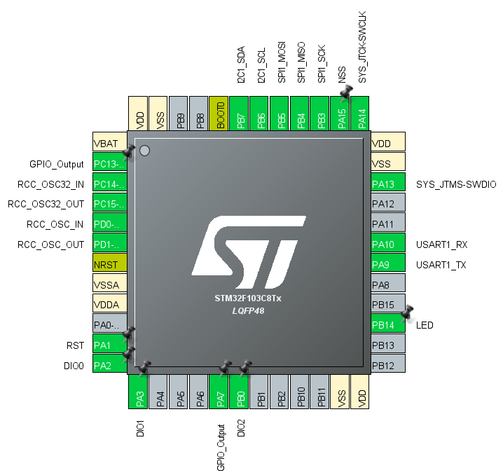
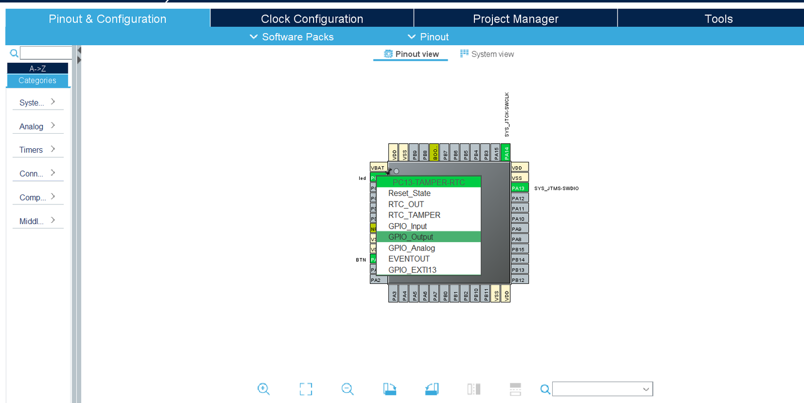
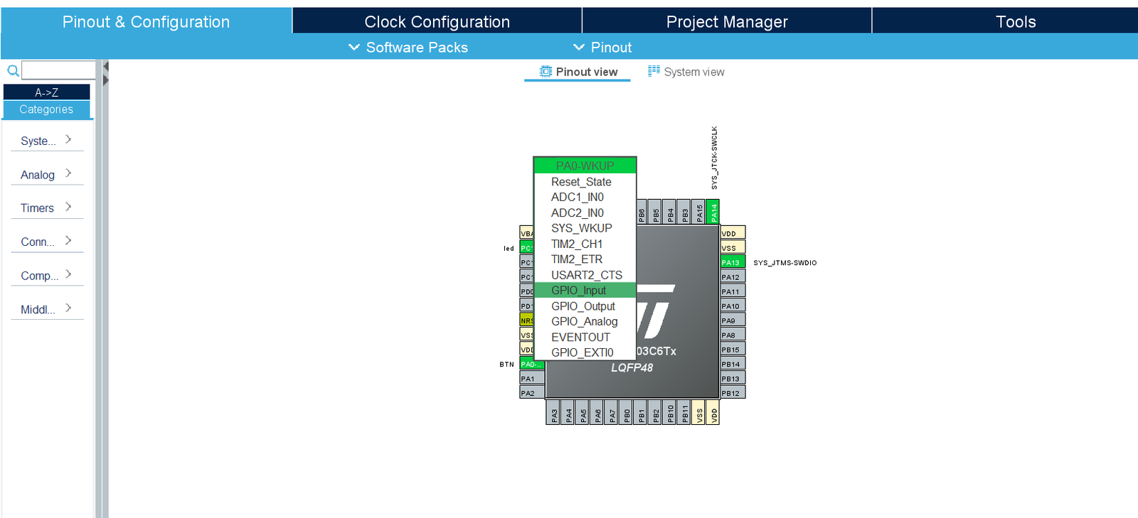
 All the pins of STM32F103 are grouped in multiple ports as PORT A, PORT B, PORT C As can be seen from Pin configuration chart in the PA1 stands for Port A Pin 1. There are 37 GPIO pins in stm32f103 which are divided as PORT A with 16 pins, PORT B with 16 pins, PORT C with 3 pins and PORT D with 2 pins.
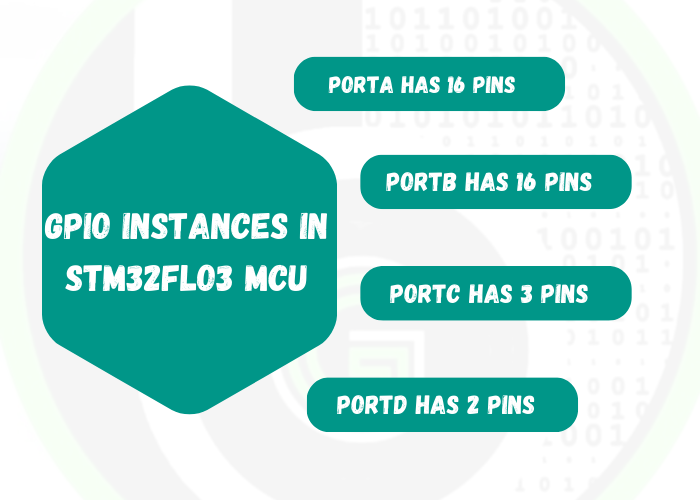
- Each GPIO port has two 32-bit configuration registers (GPIOx_CRL, GPIOx_CRH), two 32-bit data registers (GPIOx_IDR, GPIOx_ODR), a 32-bit set/reset register (GPIOx_BSRR), a 16-bit reset register (GPIOx_BRR) and a 32-bit locking register (GPIOx_LCKR).
- In the register names, x stands for the port to which pin belongs. If we are configuring pin PA1, it has Port A then registers would be accessed by GPIOA_CRL and etc.
- Out of above-mentioned registers, GPIO peripheral has 2 most important registers:
-

Direction Register(GPIOx_CRL, GPIOx_CRH)
Direction register: Set the corresponding pin as input/output pin.
-

Data register(GPIOx_IDR, GPIOx_ODR)
Data register: where we set the Logic level (High (1)/Low (0)), for the corresponding pin if it is configured as output pin or we read the Logic level (High (1)/Low (0)), for the corresponding pin if it is configured as input pin.
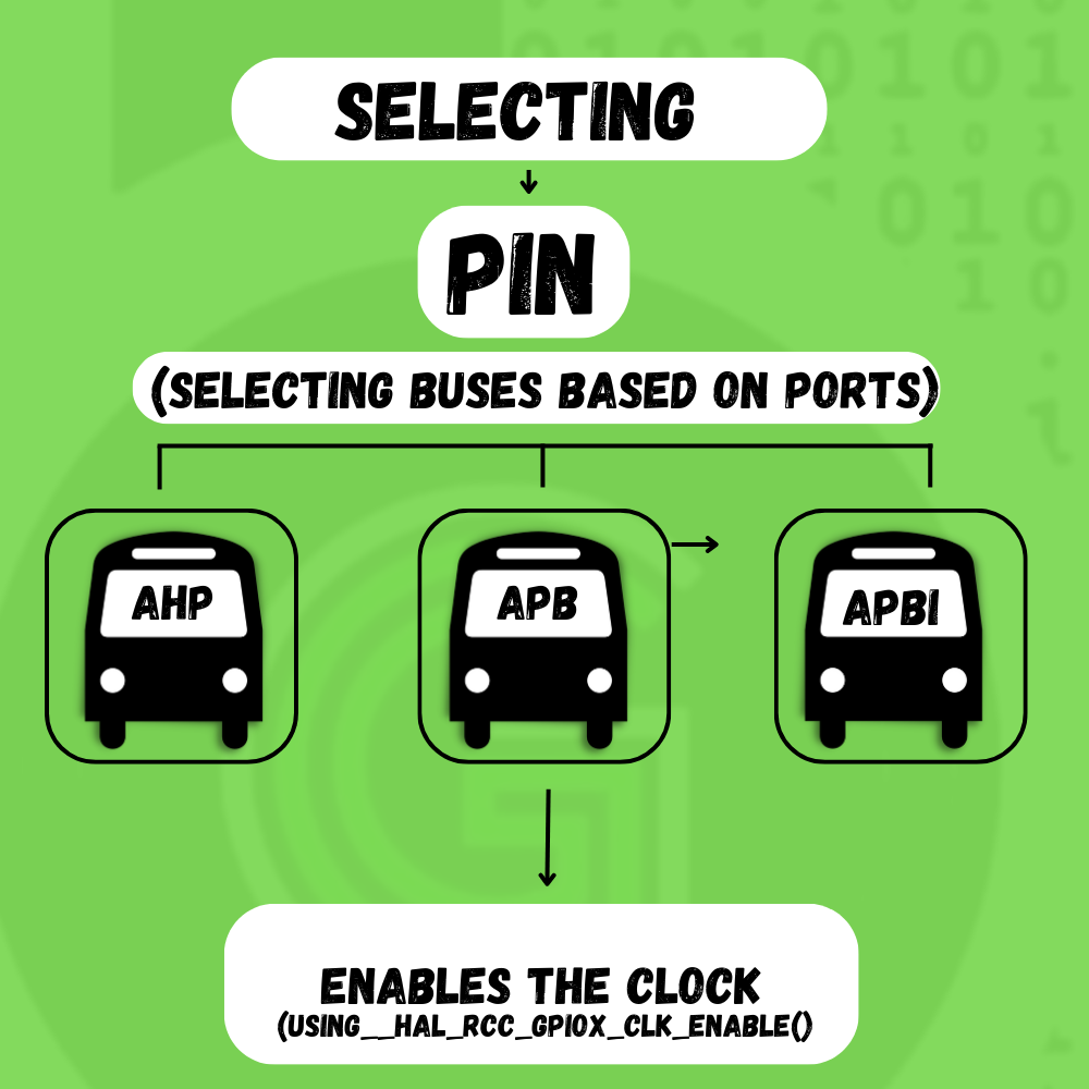
- First after selecting the pin the port is decided
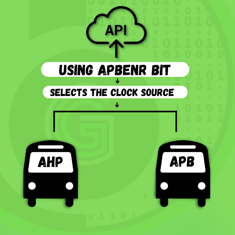
- Then after following the arrow the busses are selected based on it: APB/APB1 or AHB
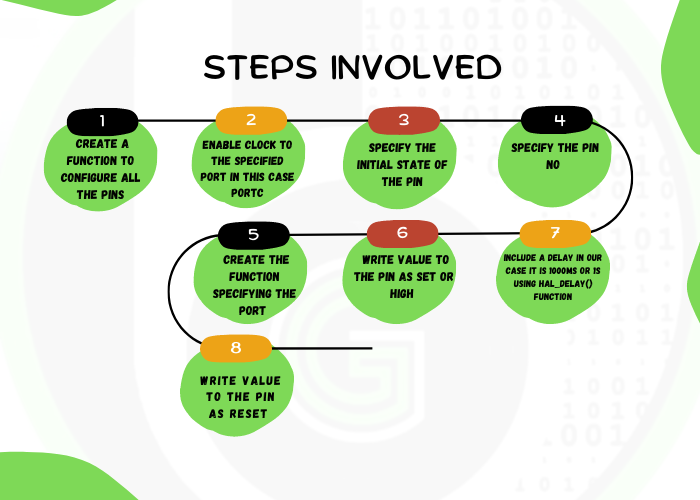
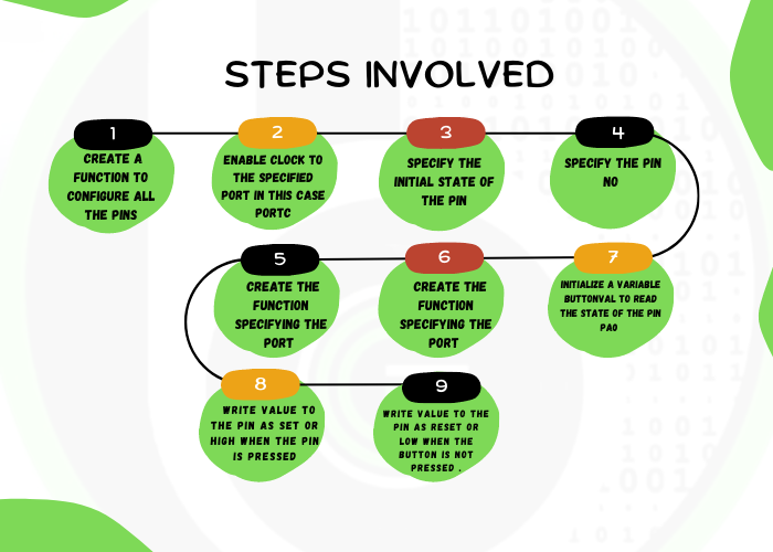
- After which the clock is enabled to the particular port using either __HAL_RCC_GPIOX_CLK_ENABLE() function or using the RCC AHB1 peripheral clock enable register and selecting the port to which clock has to be provided by enabling it.
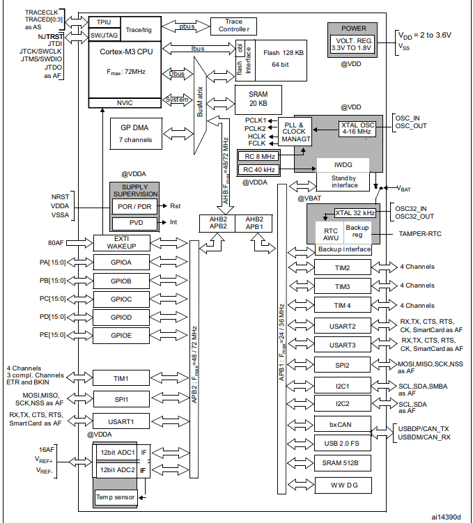
- Configuring the busses i.e AHB1, AHB2, APB1, APB2 . The AHB bus is faster than APB bus and in case of certain modules they are connected to the same bus .Hence it depends upon the application which bus to use. As can be seen from the picture below the AHB1 takes clock to PORT A , PORT B , PORT C etc . Hence to initialize a pin to a particular port the in RCC AHB1 clock enable register GPIOEN is set to 1 (For Port A GPIOAEN , For Port B GPIOBEN etc)
- Enabling the clock to that port otherwise the particular pin will not be functional
- Creating an instance of the structure and then using the members of the structure set the following:-
- PIN – Takes the pin no as input GPIO_PIN_X {where X -0 to 15}
- MODE– Selects the mode the specified pin is supposed to work in . It takes in value Output Push Pull ,Output Open drain
- PULL- It selects the initial value of the pin and takes value no pull up no pull down, pull up or pull down
- SPEED- Selects the speed of the working of the specified pin i.e low, medium or high
- ALTERNATE- Specifies the alternate function performed by the pin UART TX OR RX , ADC etc,
We are going to use STM32 HAL SDK for using the GPIO peripheral of the STM32F103. STM32HAL is a very versatile and robust Software package for using Peripherals of the STM32 Microcontroller family. To know more about STM32HAL, refer to this link.
Each STM32 HAL has drivers for all the peripherals of the STM32 Microcontroller(One can navigate to the Driver folder in the STM32F1 HAL local repo installed). These drivers can be configured and enabled to use in the project via the STM32 CubeMX configuration tool, which is also integrated into STM32CubeIDE( just like told in the above section for configuring GPIO peripherals). Will be digging into that part, in the next section. For now, let’s understand the STM32HAL GPIO SDK for STM32F103 MCU.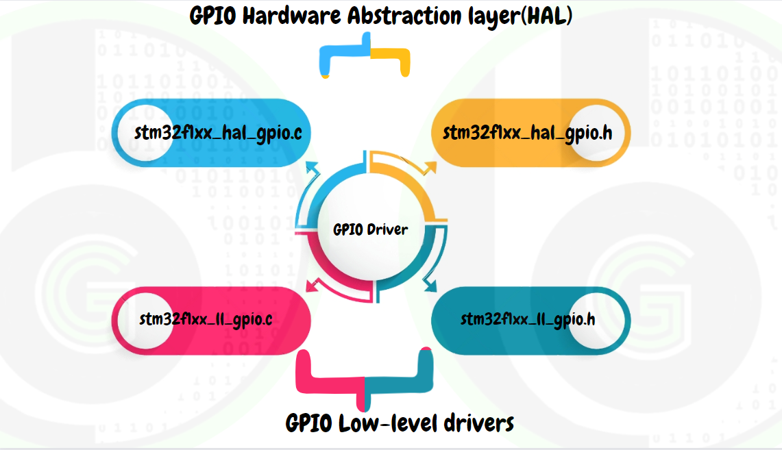
- stm32f1xx_hal_gpio.h: consists of various structure definitions that help configure various parameters of the pin, enumeration, and various macros
- stm32f1xx_ll_gpio.c & stm32f1xx_ll_gpio.h: GPIO Low-level driver source/header file, contains functions that configure the GPIO Peripheral registers at the hardware level. These files are the ones that actually interact with the hardware and make it configurable to our needs. 
Functions are set of instructions that required to perform certain tasks. In general, a function is first declared in header file(.h) and then it is definied in source file(.c) and then called in main.c or application code.
It is of the form function return data type, function name and function arguments. 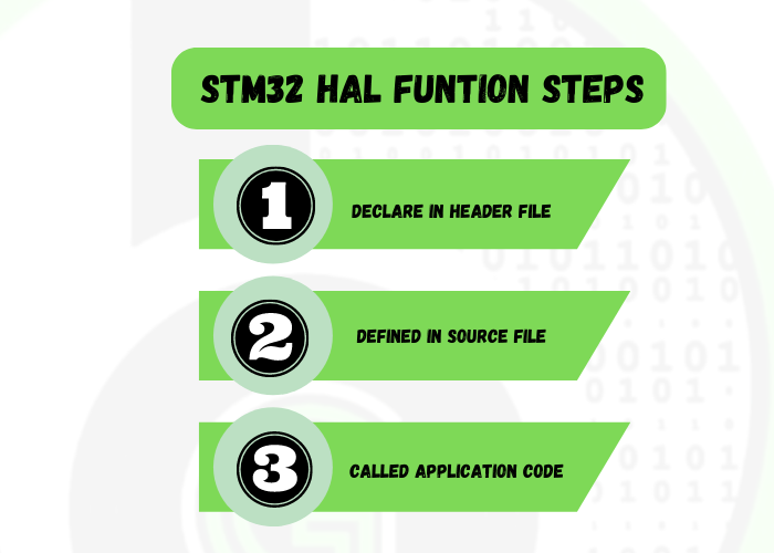
List of functions used for GPIO HAL: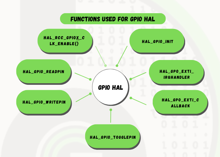
FUNCTION NAME
- void HAL_GPIO_Init (GPIO_TypeDef* GPIOx, GPIO_InitTypeDef *GPIO_Init)
FUNCTION DESCRIPTION
This API takes 2 arguments as input that are pointer to structure GPIO_TypeDef* GPIOx this is usually used to specify the port (A,B etc) and GPIO_InitTypeDef *GPIO_Init which is basically the pointer to the structure GPIO_InitTypeDef this contains information of the pin configuration such as pin , mode , speed , pull , alternate. This API basically initializes the specified pin according to configuration specified in GPIO_Init.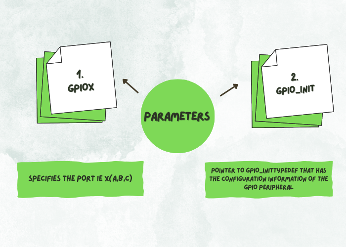
PARAMETERS (ARGUMENTS)
GPIOx:specifies the PORT ie X(A,B,C)
GPIO_Init: Pointer to GPIO_InitTypeDef that has the configuration information of the GPIO peripheral
RETURN VALUE
NONE
USAGE
FUNCTION NAME
- GPIO_PinState HAL_GPIO_ReadPin (GPIO_TypeDef * GPIOx, uint16_t GPIO_Pin)
FUNCTION DESCRIPTION
This API is used to Read the value from a specified pin and it returns value of the type GPIO_PinState which is an enumeration in which GPIO_PIN _RESET has been assigned the value 0U and anything apart from this is GPIO_PIN_SET. This API takes in 2 arguments as input that are pointer to structure GPIO_TypeDef* GPIOx this is usually used to specify the port (A,B etc) and uint16_t GPIO_Pin this specifies the pin to be chosen and takes value from 0-15.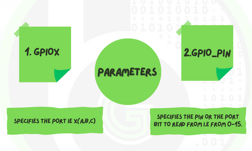
PARAMETERS (ARGUMENTS)
GPIOx:specifies the PORT ie X(A,B,C)
GPIO_Pin:specifies the pin or the port bit to read from i.e from 0-15.
RETURN VALUE
The input pin state value
USAGE
FUNCTION NAME
void HAL_GPIO_WritePin (GPIO_TypeDef * GPIOx, uint16_t GPIO_Pin, GPIO_PinState PinState)
FUNCTION DESCRIPTION
This API is used to write either a HIGH or LOW at the specified pin . It takes in 3 arguments as input that are pointer to structure GPIO_TypeDef* GPIOx this is usually used to specify the port (A,B etc) , uint16_t GPIO_Pin this specifies the pin to be chosen and takes value from 0-15 and GPIO_PinState PinState which is an enum of the type GPIO_PinState which takes in value SET or RESET.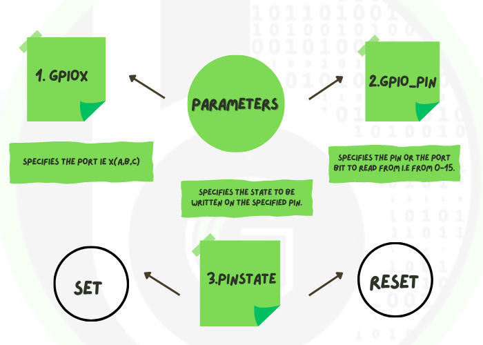
PARAMETERS (ARGUMENTS)
GPIOx:specifies the PORT ie X(A,B,C)
GPIO_Pin:specifies the pin or the port bit to read from i.e from 0-15.
PinState:specifies the state to be written on the specified pin.These values are:
SET- To write a HIGH on the pin
RESET- To the clear or write LOW on the pin
RETURN VALUE
NONE
USAGE
FUNCTION NAME
void HAL_GPIO_TogglePin (GPIO_TypeDef * GPIOx, uint16_t GPIO_Pin)
FUNCTION DESCRIPTION
This API is used to toggle or switch the state of the specified pin high to low or low to high. This API also takes in 2 arguments as input that are pointer to structure GPIO_TypeDef* GPIOx this is usually used to specify the port (A,B etc) and uint16_t GPIO_Pin this specifies the pin to be chosen and takes value from 0-15.
PARAMETERS (ARGUMENTS)
GPIOx:specifies the PORT ie X(A,B,C)
GPIO_Pin:specifies the pin or the port bit to read from i.e from 0-15.
RETURN VALUE
NONE
USAGE
NOTE-The above exercise can also be performed by replacing the 2 HAL_GPIO_WritePin(led_GPIO_Port, led_Pin, GPIO_PIN_SET), HAL_GPIO_WritePin(led_GPIO_Port, led_Pin, GPIO_PIN_RESET) with the HAL_GPIO_TogglePin(led_GPIO_Port, led_Pin) and since the HAL API is called in the while loop the led will blink forever in a loop.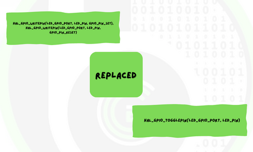

ADC Peripheral in Microcontroller’s
Explore about ADC peripheral in Microcontroller from foundational and functional level

Getting started with AVR and Arduino
Home Category Child Category Part I – Untangling the wires: On your journey of exploring the different areas of embedded
Keypad Module in Embedded
Table of Contents What are Keypad Modules ? Keypads are input devices that most of us are familiar with that
AutoBoardV1 Automotive Board ( HSM Crypto Peripheral +Ethernet)
Low-Cost Automotive Evaluation Board for S32K344
ElecronicsV3 Automotive Board (SHE Crypto Peripheral + CAN)
Low cost Development Board for NXP S32K144 MCU as beginner friendly automotive kits
Timer Peripheral in S32K144 Microcontroller
About FlexTimer Module: Timer peripheral in NXP S32K1xx and S32K3xx Automotive Microcontrollers