
Imagine you’re handed a powerful little board, no bigger than your palm. At first glance, it looks like a jungle of chips, ports, and connectors. But as you lean in, it starts to unfold its story — a tale of real-time intelligence, fast interfaces, and the future of edge computing.
Let me introduce you to the FRDM i.MX93 development board, NXP’s latest offering to developers stepping into the world of AI at the edge.
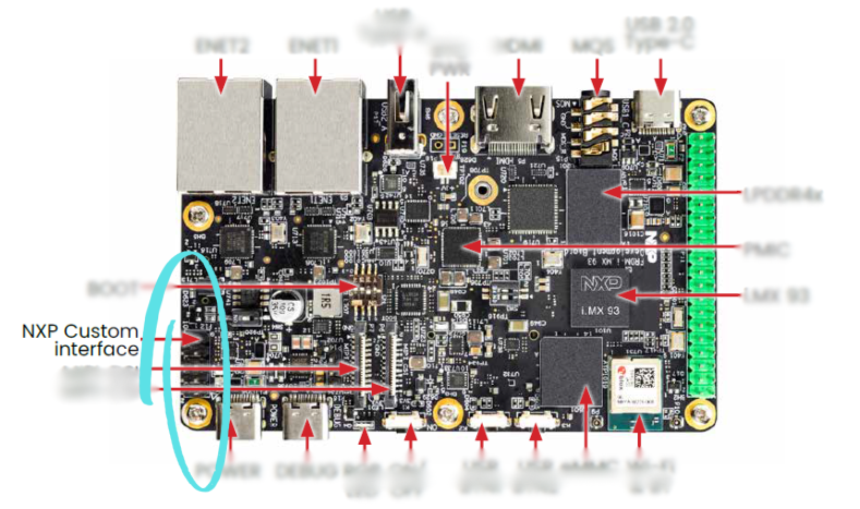
The Gateway Ports: Connectivity First
As with any explorer, your journey begins at the edges of the board — literally.
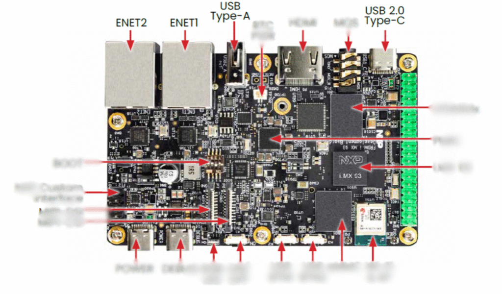
- USB Type-A and USB Type-C Ports
These are your main lifelines. The USB Type-A port lets you connect a USB camera, a keyboard, or even storage devices. Meanwhile, the USB 2.0 Type-C port serves both as a power input and a data port. If you’re flashing firmware, logging in via serial console, or powering up the board — this is where the action starts. - ENET1 & ENET2 (Ethernet Ports)
Need wired internet for real-time inference or fast updates? The dual Gigabit Ethernet ports have you covered. One can be for your local dev environment, while the other connects directly to the cloud.
Power, Buttons, LEDs & Debugging Tools
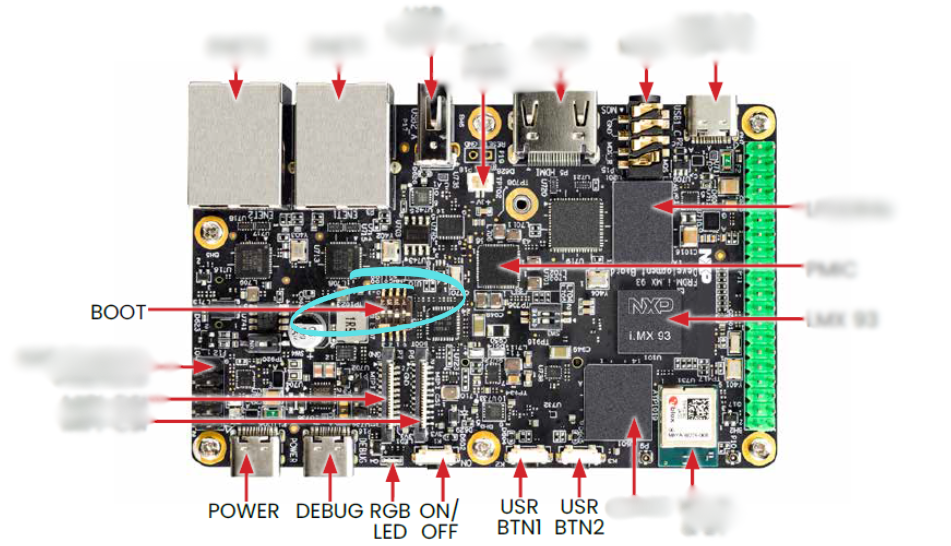
Just beneath the ports, you’ll notice a row of control, diagnostic, and power features — the tools that help you bring your board to life and keep an eye on its every move:
- POWER Port – The dedicated source that supplies juice to the entire system. Whether you’re using USB Type-C or a barrel jack, this port ensures your board stays alive and responsive.
- DEBUG Port – Your window into the board’s brain. Connect it to a JTAG or SWD debugger to step through code, inspect registers, or troubleshoot boot sequences with precision.
- POWER Button – The simplest way to bring your board to life.
- DEBUG RGB LED – A color-coded signal light that can be programmed to reflect states: boot complete, inference in progress, errors, etc.
- ON/OFF Button – Works in tandem with the PMIC (Power Management IC) to soft-power the board.
- BOOT Button – Helps you enter bootloader mode for flashing firmware or switching between boot sources.
- USR BTN1 and BTN2 – Two user-programmable buttons. Think of them as triggers — for manual inference, mode switching, or anything else your application dreams up.
Understanding Boot Modes on the i.MX93: Choose Your Core, Choose Your Path
The i.MX93 is not just powerful — it’s flexible. At its heart are two processing cores:
Cortex-A55 (Application Processor)
Cortex-M33 (Real-Time Microcontroller)
Depending on your use case — whether it’s edge AI, boot-time performance, or minimal power draw — you can choose which core to boot from first.
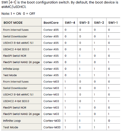
This choice is configured using the SW1 DIP switch on the board, specifically SW1[4:1], which sets the boot mode.
Each switch can be either:
1 = ON0 = OFF
Here’s a breakdown of boot options and what each does:
Cortex-A55 Boot Modes
| Boot Mode | What It Means |
|---|---|
| From internal fuses | Boots from permanent configuration burned into fuses. |
| Serial Downloader | Boots into USB/Serial mode for flashing/debugging. |
| USDHC1 8-bit eMMC 5.1 | Boot from 8-bit eMMC via USDHC1 interface (usually internal storage). |
| USDHC2 4-bit SD3.0 | Boot from SD card (like when you flash a Yocto image). |
| FlexSPI Serial NOR | Boot from external NOR flash via FlexSPI. |
| FlexSPI Serial NAND 2K page | Boot from NAND flash memory with 2K pages. |
| Infinite Loop | System enters a loop (for test/debug). |
| Test Mode | Special test/debug mode (avoid using in real deployments). |
These modes are ideal when you want full Linux support, camera AI processing, or anything requiring high performance.
Cortex-M33 Boot Modes
| Boot Mode | What It Means |
|---|---|
| From internal fuses | Like Cortex-A55, but boots directly into M33 for real-time tasks. |
| Serial Downloader | Flash/debug the Cortex-M33 directly. |
| USDHC1 8-bit eMMC 5.1 | Boot M33 from eMMC. Useful for M33 bare-metal applications. |
| USDHC2 4-bit SD3.0 | Boot M33 from SD card (lower-level RTOS or bare-metal). |
| FlexSPI Serial NOR | Boot from external NOR via FlexSPI. Great for embedded firmware storage. |
| FlexSPI Serial NAND 2K page | Boot M33 from NAND flash memory. |
| Infinite Loop | Debug/testing loop for Cortex-M33. |
| Test Mode | Reserved for internal test/debug. |
Use these modes when you’re building ultra-low-power embedded apps, real-time control, or using the M33 as a co-processor to the A55.
How to Set These Modes
The SW1 DIP switch on the FRDM i.MX93 board has four relevant bits:
SW1-4 = MSB
SW1-1 = LSB
For example:
If you want to boot from SD card on Cortex-A55, set:
0100For Serial Downloader on Cortex-M33, set:
1101
Vision, Display, and Multimedia
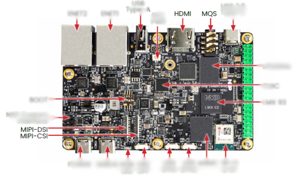
The i.MX93 isn’t just about processing — it’s about seeing and displaying.
- MIPI-CSI & MIPI-DSI Interfaces
Want to use a camera module instead of USB? The MIPI-CSI connector handles high-quality image input from dedicated sensors. On the flip side, the MIPI-DSI connector drives compact display panels — useful for AI applications with touch screens or HUDs. - HDMI Out
Need a monitor? Plug in via HDMI to visualize inferences, stream logs, or simply debug in style. - MQS Audio Jack
For audio edge AI or just multimedia playback, the Miniature Quality Sound (MQS) interface provides simple stereo output — plug in your speakers or headphones.
The Brains: i.MX93 + Ethos-U65 + M33
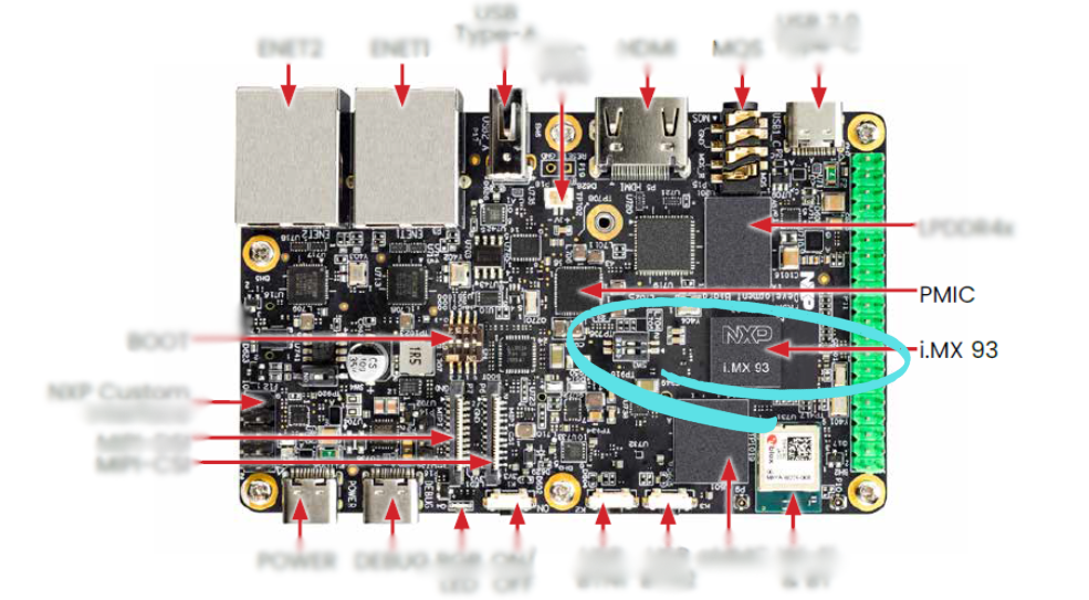
Now let’s zoom into the heart of the board.
- i.MX 93 MPU (Microprocessor Unit)
This is the main SoC — a dual-core Arm Cortex-A55 system paired with an embedded Ethos-U65 NPU. It’s optimized for AI inference at the edge, balancing performance with power efficiency. - Arm Cortex-M33 Core
Quietly working alongside the A55, the M33 microcontroller handles low-latency real-time tasks — like reading sensors, handling GPIOs, and managing peripherals — without burdening the main processor.
It is embedded inside the i.MX 93 SoC (marked on the board as “i.MX 93”). You won’t see it physically labeled on the PCB because it’s part of the silicon die. - Ethos-U65 NPU (Neural Processing Unit)
A game-changer for low-power AI. It accelerates INT8 models (and more) so you can run deep learning tasks like image classification or object detection — all in real-time, on the edge.
Again, it’s integrated inside the i.MX 93 SoC — there is no separate chip or label.It’s part of NXP’s AI-enabled architecture to accelerate ML inference tasks at the edge. - PMIC (Power Management IC)
This smart controller distributes power across the board intelligently — from high-draw peripherals to sleep-ready subsystems.
Memory, Storage, and Expansion
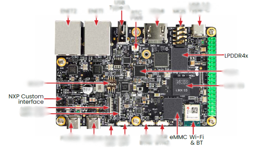
- LPDDR4x RAM
Efficient, fast, and low-power — this RAM ensures your AI workloads don’t get bottlenecked. - eMMC Flash
Persistent onboard storage for your OS (Yocto Linux), model files, logs, and scripts. It’s rugged and reliable for embedded use. - Wi-Fi & Bluetooth Module
Wireless communication made easy — whether you’re sending results to a cloud server or controlling the board via smartphone. - NXP Custom Interface Header
Need extra I/O, SPI, I²C, or GPIO? This expansion header is a playground for custom sensors and peripherals.
We will explore its capabilities and applications in detail further in this blog.
A Peek Beneath: Bottom View of the FRDM i.MX93 Board
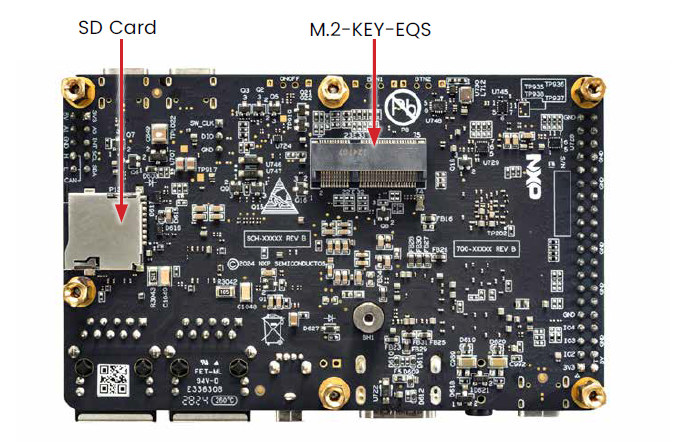
1. SD Card Slot – Expandable and Boot-Friendly
Located on the bottom-left corner, the SD Card slot allows developers to insert a microSD card. This isn’t just for storing files — you can:
Boot your board directly from the SD card (when set via boot switches).
Use it as external storage for datasets, logs, or multimedia files.
Quickly swap firmware or test different operating systems without re-flashing the onboard memory.
This makes it an essential feature for rapid prototyping, field updates, or offline applications.
Developers often use the SD card slot during early development or field updates where re-flashing via USB isn’t feasible.
2. M.2 KEY-EQS Connector – Open Doors to Expansion
Sitting at the center-top area of the board’s underside is the M.2 KEY-EQS slot. This connector empowers developers to expand the board’s capabilities by adding compatible M.2 modules. For instance:
Add Wi-Fi or Bluetooth modules for wireless connectivity.
Insert AI acceleration modules for more advanced edge computing.
Utilize high-speed data communication via PCIe or USB interfaces (based on the module used).
“KEY-EQS” means it follows the Key-E signal layout – often used for wireless modules and some embedded AI accelerators.
Unlocking Connectivity: The 40-Pin Raspberry Pi-Compatible GPIO Header
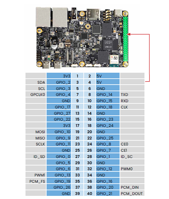
The FRDM i.MX93 development board comes equipped with a 40-pin GPIO header, just like the Raspberry Pi, making it easy to adapt existing Pi-compatible accessories and HATs (Hardware Attached on Top).
Let’s break down what makes this header powerful for developers and prototypers alike:
Power Pins
3V3 (Pins 1, 17) and 5V (Pins 2, 4) provide regulated voltage rails.
GND pins are scattered across the layout (e.g., pins 6, 9, 14, etc.) for stable grounding.
These ensure that sensors, modules, and external devices are powered safely and reliably.
Communication Protocols
I2C (Inter-Integrated Circuit):
SDA – GPIO_2 (Pin 3)
SCL – GPIO_3 (Pin 5)
Useful for connecting multiple low-speed peripherals like temperature sensors or OLED displays with just two wires.
UART (Universal Asynchronous Receiver-Transmitter):
TXD – GPIO_14 (Pin 8)
RXD – GPIO_15 (Pin 10)
Perfect for serial communication with modules like GPS, Bluetooth, or debugging over serial terminal.
SPI (Serial Peripheral Interface):
MOSI – GPIO_10 (Pin 19)
MISO – GPIO_9 (Pin 21)
SCLK – GPIO_11 (Pin 23)
CE0/CE1 – GPIO_8 (Pin 24), GPIO_7 (Pin 26)
Enables high-speed communication with sensors, SD cards, or displays.
PCM/I2S (Audio Interface):
PCM_FS – GPIO_19 (Pin 35)
PCM_DIN – GPIO_20 (Pin 38)
PCM_DOUT – GPIO_21 (Pin 40)
Great for connecting digital microphones, DACs, or audio streaming hardware.
GPIO – General Purpose Input/Output
All blue-highlighted pins labeled as GPIO_xx (e.g., GPIO_5, GPIO_13, GPIO_18) can be programmed as digital inputs or outputs. This means you can use them to:
Read button presses
Control LEDs, motors, or relays
Trigger sensors or alarms
Implement interrupt-based logic
PWM Support
PWM0 – GPIO_12 (Pin 32)
PWM1 – GPIO_13 (Pin 33)
PWM (Pulse Width Modulation) is useful for applications like servo control, dimming LEDs, or generating variable analog-like signals.
Why This Matters?
This 40-pin header makes the FRDM i.MX93 developer-friendly and Pi-compatible, opening doors to a rich ecosystem of accessories and enabling projects that require multiple I/O interfaces — all on one board.
NXP Custom Interface Header – A Playground for Custom Sensors and Peripherals
The NXP Custom Interface Header on the FRDM i.MX93 development board provides developers with a powerful, flexible way to extend the board’s capabilities beyond the standard GPIO header. It’s designed to give you access to additional I/O signals, multiple serial interfaces, and custom functionality that are essential for real-world applications involving sensors, actuators, and communication peripherals.
What Can You Do with the Custom Header?
This 20-pin interface (located on the left side of the board near the MIPI connectors) allows you to:
1. Access Extra GPIOs
Use extra General Purpose I/O pins to connect to LEDs, switches, buzzers, or other low-speed digital components.
Useful when the main GPIO header is already populated or reserved for specific tasks.
2. I²C Communication (Inter-Integrated Circuit)
Easily interface with low-speed peripherals like temperature sensors, real-time clocks (RTC), EEPROMs, etc.
The board supports I²C master/slave configuration, ideal for multi-device sensor networks.
3. SPI Communication (Serial Peripheral Interface)
Connect high-speed peripherals like displays, memory modules, and digital sensors.
Offers fast full-duplex communication, making it suitable for real-time applications.
4. UART / Debug / Console Interface
Use the header for serial communication (UART) with external modules such as GPS, Bluetooth, or GSM/GPRS modules.
Ideal for logging, command-line interfaces, or bootloader flashing/debugging.
5. Flexible Multiplexing
NXP’s IOMUX configuration allows many pins to be remapped for different functions (SPI/I²C/GPIO/UART) depending on your firmware and project needs.
Why Is This Header Useful?
The standard Raspberry Pi-compatible GPIO header provides general-purpose interfaces, but when you’re building complex embedded systems, you often need more peripherals or alternate signal routing. The NXP Custom Interface Header addresses this need, allowing engineers to:
Prototype advanced hardware solutions quickly.
Attach custom HATs (Hardware Attached on Top) or extension boards.
Enable modular development – e.g., attach a sensor board during testing, then replace it with a different one without touching the main board.
Use Case Examples:
Custom Sensor Board: Connect a custom PCB with multiple gas, air quality, or motion sensors over I²C and GPIO.
Display Interface: Attach a secondary SPI screen for diagnostics or dual-display applications.
External Control: Connect relays, solenoids, or other actuators using GPIO and PWM signals.
Custom HATs: Design a stackable board for AI/ML inference or robotics control using UART and GPIO.
The Lab on Your Desk
The beauty of the FRDM i.MX93 board is its balance. You get:
The compute of Cortex-A55
The precision of Cortex-M33
The acceleration of Ethos-U65
And the flexibility of full I/O, USB, HDMI, Wi-Fi, and more
Whether you’re prototyping an AI-powered safety helmet detector, building a smart camera system, or deploying real-time inference on-site, the i.MX93 turns your desk into a full-fledged AI lab.
Wrapping Up: Your AI Journey Begins
As you explore each chip and connector on the i.MX93, you’re not just handling a piece of hardware. You’re unlocking the future of embedded AI — one where machines can see, think, and respond — right at the edge.
So plug in that USB cable, flash your model, and watch it come alive. The board is ready. Are you?