
Overview
In microcontroller to use CAN technology, there is a CAN Controller which handles CAN communication and follow CAN standards of ISO-11898 to support CAN protocol and its features. CAN Controller can be of 2 types CAN peripheral in Microcontrollers or some external CAN IC. So now in this blog, we are going to dig deep into general understanding of CAN Controller which are either present in the form of CAN Peripheral in microcontroller or some External CAN IC. We are going to focus on CAN Peripheral for examples given. But same understanding would be their for External CAN IC.
In different Microcontrollers there is a CAN peripheral, that can be referenced by different names. Like in NXP S32K1 and S32K3 MCU’s it is FlexCAN Module, in Infineon Technologies TC3xx MCU it is MCMCAN module. And multiple instances of corresponding CAN peripheral, can be present in a corresponding MCU. In NXP S32K1xx there are 3 instances of FlexCAN module. In Infineon TC3xx there are 5 instances on MCMCAN module. The peripherals can be termed as different names in different microcontroller, but their basic working and concept is same in all. So, it’s important that we understand how CAN peripheral in a microcontroller works.
Understanding the working of CAN peripheral of a microcontroller, make us get knowledge on how to use CAN technology in practical sense. Relating theoretical concepts of CAN technology like multi-bus protocol, error managment, Standard/Extended CAN Data Frames communication techniques, Transmission/Reception of different data frames of CAN with practical DIY projects, is best done by understanding how CAN peripheral in a microcontroller works and then doing simple DIY projects to test different features of that technology.
How does CAN peripheral in microcontroller’s work for doing CAN communication? How to do simple 2-way CAN communication from microcontrollers? How CAN transmission happens? How CAN reception happens? How to configure Microcontroller for CAN transmission and CAN reception? How to do CAN communication via different techniques(polling/interrupt/DMA)? How standard/extended/CAN FD communication configurations are done?
In CAN peripheral there are concept of Message buffer, Mailboxes, Rx FiFo, FiFo message ID filter table and CAN protocol engine which are used for transmission and reception of CAN data. These concepts are important to understand. These concepts are implemented in CAN peripherals and external CAN ICs via which transmission and reception of CAN data frames happen at microcontroller and embedded level. However, the nature of implementations of these concepts in CAN peripherals can be different and would be SoC dependent. Understanding of this concept is important from Embedded Software point of view and if you want to have some Handson project and learning on CAN protocol.
What are Message buffers in CAN Controllers?
Well now in CAN peripheral of the microcontroller’s, there is a small section of memory in microcontroller that is being used to process the CAN data. This memory is called as message buffer. Buffer signifying for memory and message signifying for CAN data. All CAN Transmitted and received data is processed in this message buffer space only. The message buffer can be referenced as Embedded RAM or Memory RAM in different SoC. But all terminologies meant same thing.
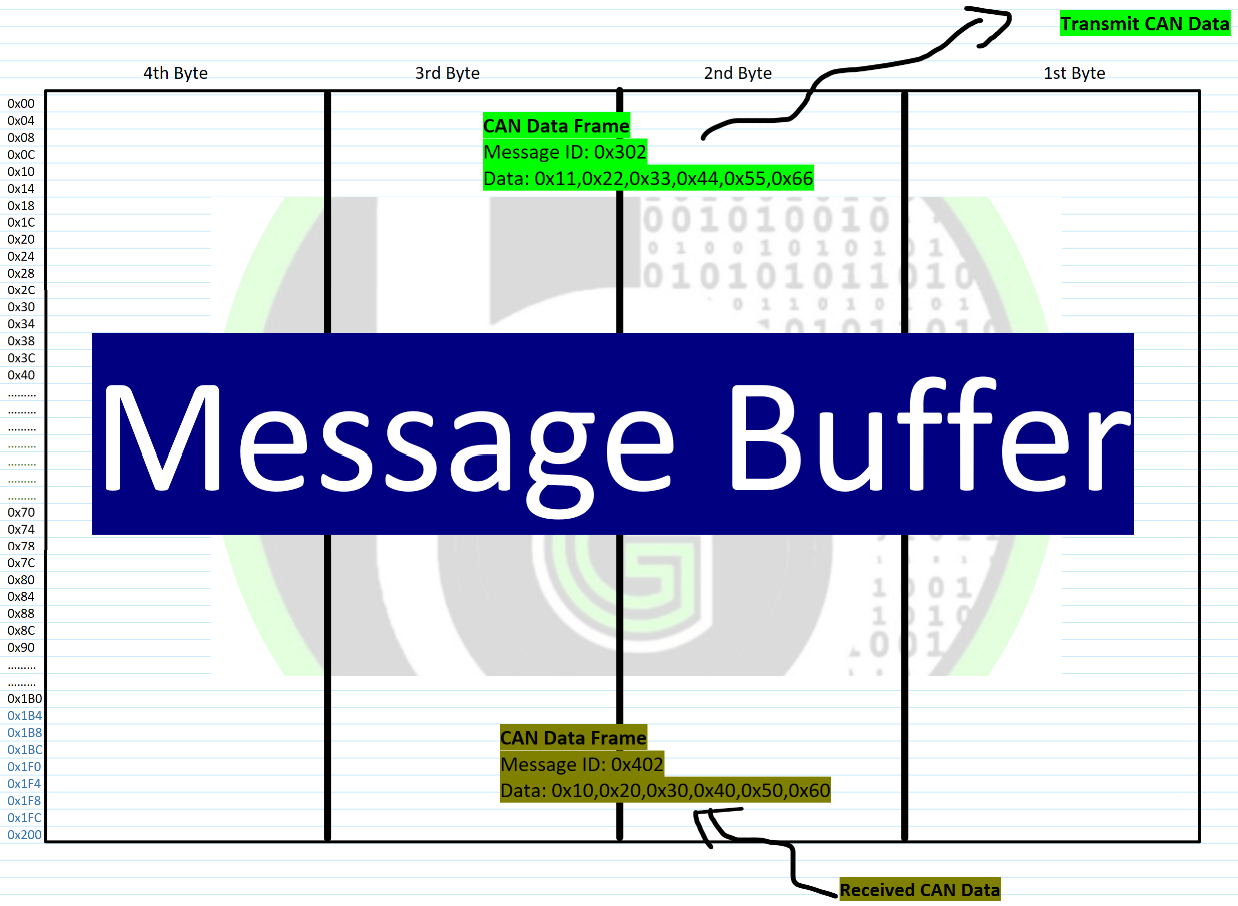
The message buffer will process all kinds of CAN Data : Standard CAN, Extended CAN, CAN FD messages. All the CAN transmission and reception of CAN data happens via the message buffer space only.
A standard CAN data is of 13.5 bytes in total, which we will near about 16 bytes to align it to
microcontroller buses. Extended CAN data is of exact 16 bytes in total, in which 8 bytes are of
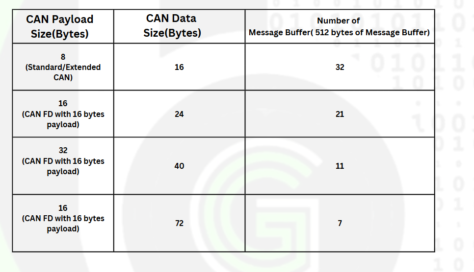
payload. Similar way in the case of CAN FD data, it occupies 16, 24, 40 or 72 bytes in total in
which 8, 16, 32, 64 bytes are payload. Though CAN FD data frames are of 14, 22, 38, 70 bytes in
total but for aligning these bytes with microcontroller busses, these are rounded off to nearest
8 multiples.
About Mailbox in CAN Controllers.
Now number of sections in a message buffer is, equal to space of message buffer divided by CAN data frame size. Each of this section is signified by a Mailbox(also called as Message Object.) Each section of the message buffer is referenced by a integer number, which is called a mailbox number.
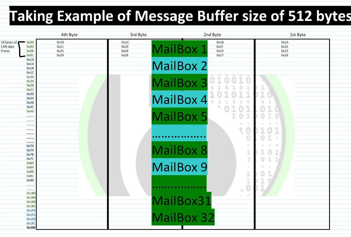
So, for address 0x00 to 0x10(16 bytes) in message buffer, it is referenced by Mailbox number 1. From 0x10 to 0x20 it will be referenced by Mailbox number 2. 0x30-0x40 -> mailbox number 3 and 0x40-0x50 -> mailbox number 4 and so on. So, we have kind of assigned a mailbox number to the different address spaces of message buffer. So, when using mailbox mechanism, their would-be linear sections of memory that are incremented according to CAN data size and each section is referenced by mailbox number.
So now if we are processing Standard CAN, Extended CAN or CAN FD with 8 bytes payload: 16 Bytes of message buffer space is what is going to be consumed for a single Data Frame, whether it is for transmission or reception. So, total there can be 32 sections of memory if we have 512-byte size of message buffer (in the case of S32K144 Microcontroller) and 96 sections of memory if we have 1536 bytes size of message buffer(In the case of S32K344 Microcontroller).
Also Depending upon the CAN payload bytes, we can have different number of mailboxes as more the payload size in a CAN frame, more size would be of overall single CAN Frame.
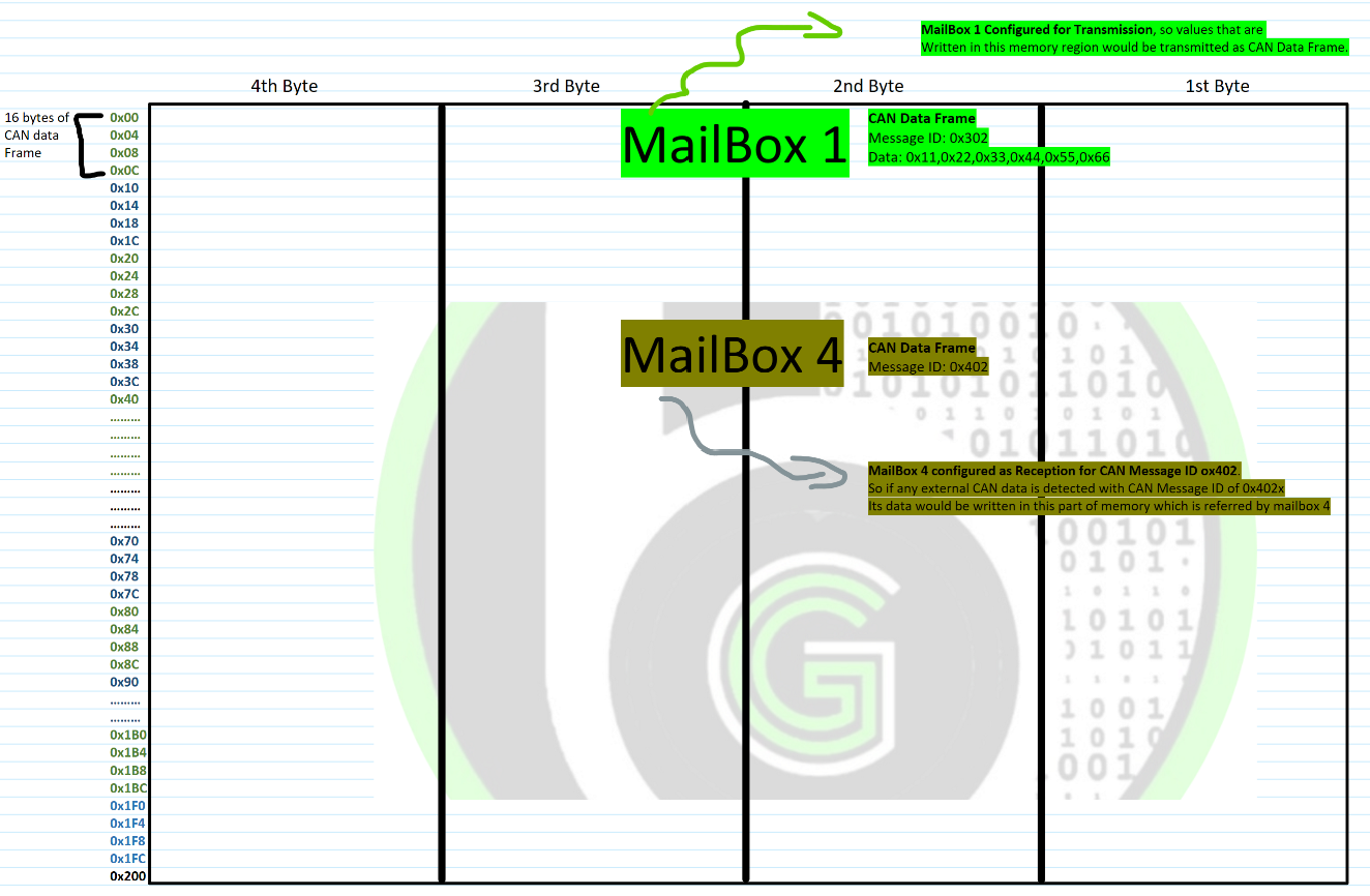
As each mailbox signifies a memory of message buffer. So we can configure a mailbox to be used for transmission of CAN data or we can configure a mailbox to be used for receiving of CAN data. Thus that how via mailbox mechanism we get configuration flexibility for transmitting and receiving feature of CAN protocol achived.
What is Mailbox in CAN Controller?
The terminology which is used to refer to one section of memory of message buffer space is Mailbox. And we can configure whether this mailbox has to be used for CAN transmission or CAN reception. In the case of CAN transmission, it would be termed as TX mailbox and in the case of CAN reception it would be termed as RX mailbox.
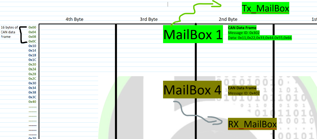
Data to be transmitted by Tx mailbox follows the arbitration process to transmit the data, and the external signal transmitted is received by Rx mailbox if message ID of external signal matches with the message ID of Rx Mailbox.
How Tx mailbox works?
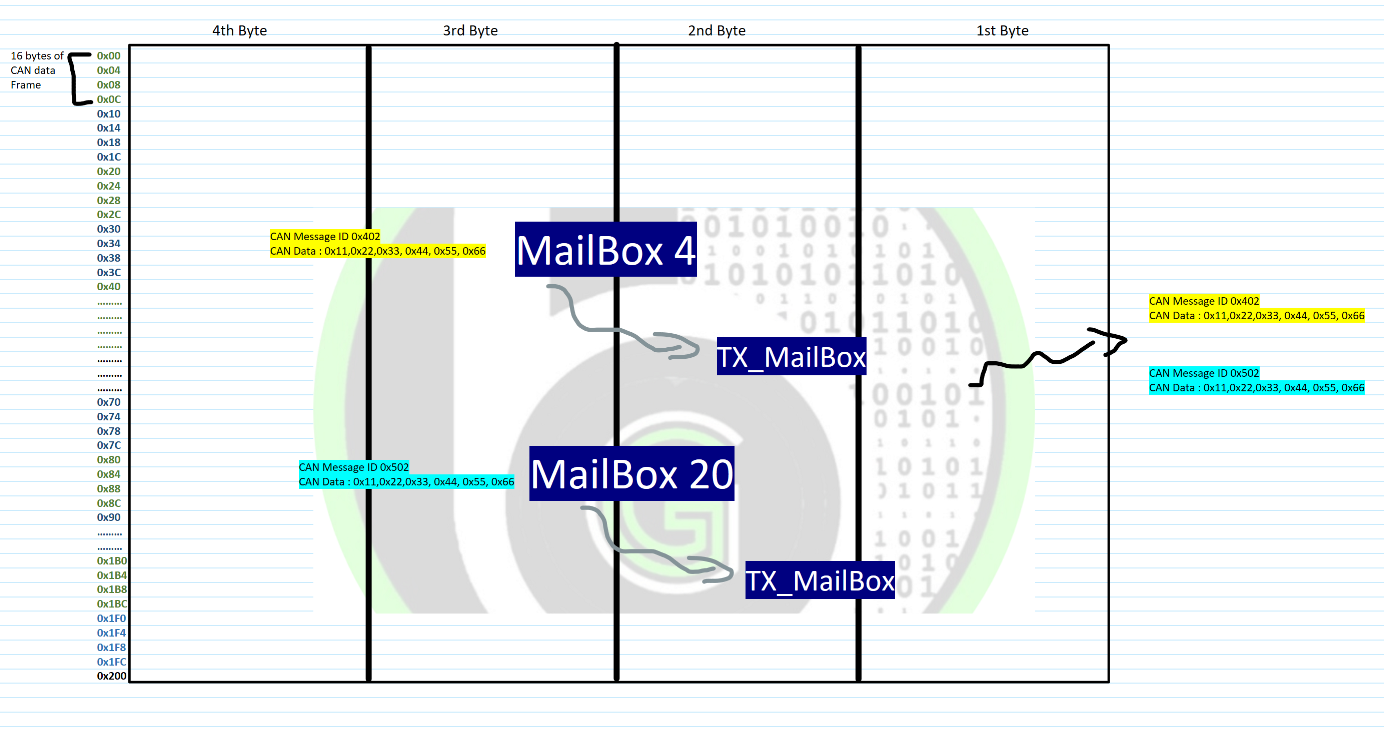
Now mailbox signifies a section of memory in message buffer, where CAN data can be written from Microcontroller in the case of transmission. So, We can bind a section of memory or what we can call a mailbox with one CAN message ID. Whenever Microcontroller calls that mailbox, configured CAN message ID with its data content would be transmitted.
In the case of transmission there are 2 important concepts to understand. First is arbitration and second is transmit priority.
Transmit priority: We can configure multiple mailboxes with different message IDs to transmit different CAN data. Now we can configure the order of transmission of those mailboxes. Which mailbox would be transmitted first, and which would be transmitted last. The CAN Controller has this feature to configure the order of transiting mailboxes. Via this feature of Tx Mailbox, another CAN priority of prioritization messages is achived.
Transmit Arbitration:
How Rx mailbox works?
In the case of reception, we can bind a mailbox with a CAN message ID. And whenever a external CAN data of that message ID is received, the CAN data is copied to the memory that is being signified by mailbox.
So, say we want to receive 2 CAN data of 0x402 message ID and 0x502 message ID. So, we can assign mailbox number 4 to 0x402 and mailbox number 20 to 0x502. Whenever CAN messages of this message ID is received by MCU, the memory that is signified by corresponding mailboxes would be filled with CAN received Data.
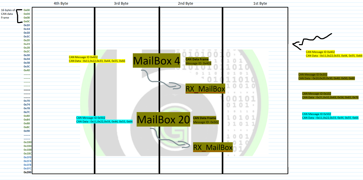
Now in a car a single ECU receives number of CAN data. So, we have to configure new mailbox for each CAN message ID that we want to receive.
This process might feel like it gives all the nodes a ‘master importance’, but it only adds to unwanted traffic towards every module on the bus in practicality. When connected to a CAN bus, the data logger acts as another node. Logging all the traffic in the CAN bus fills up the internal storage quickly. Finally, you may end up having no storage left to log the data when the vital/required data is transmitted in the bus.
Interrupt in MailBoxes
About FiFo buffer in CAN Controller?
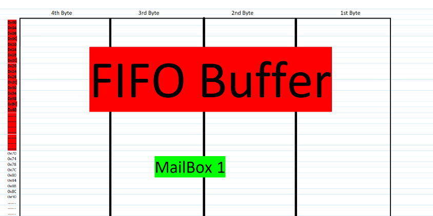
There is one more way to divide the sections of memory buffer. That is using FiFo buffer. What we do is we will configure a memory section of message buffer to be used as FiFo buffer.
How FiFo mechanism works?
What happens in FIFO buffer is that, a buffer is created and only that buffer space is used for receiving and transmitting the data. We don’t configure different memory sections or mailbox numbers for transmitting/receiving CAN data. So First Come First Out mechanism is implemented, which ever configured CAN data comes first would be process first further.
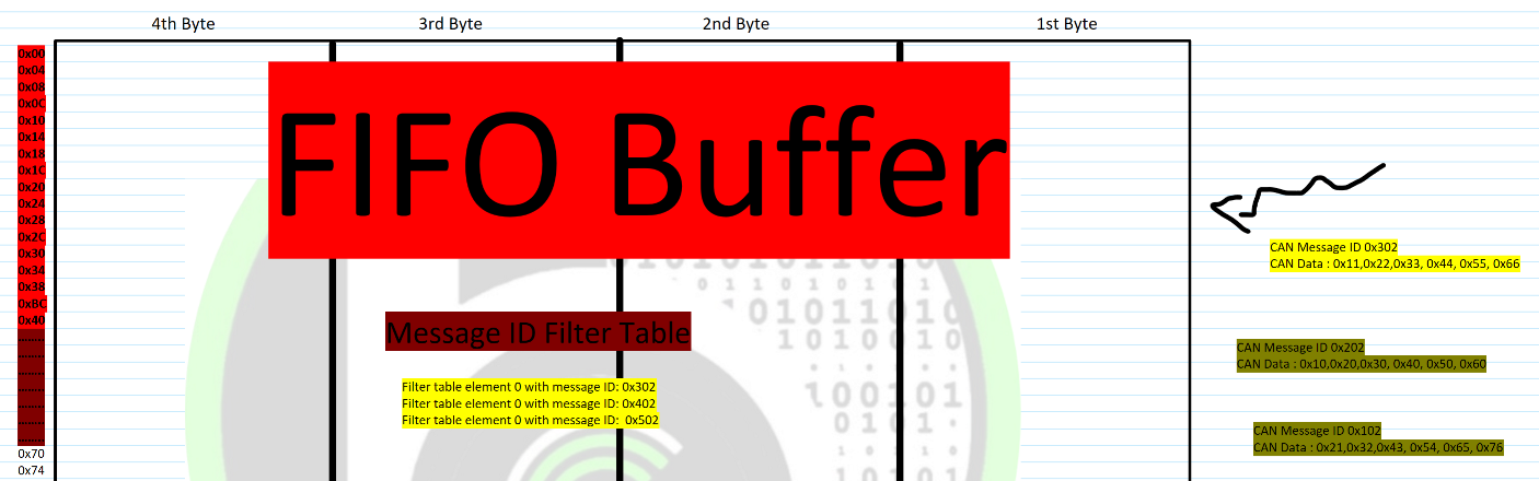
In the case of reception, it is called as Rx FiFO and in the case of transmission it is called Tx FiFo. In FiFo mode, we create a Message ID filter table or Message ID transmit table in message buffer memory. These tables would be stored with CAN message ID’s that should be accepted (in the case of receiving) or transmitted (in the case of transmission) by MCU.
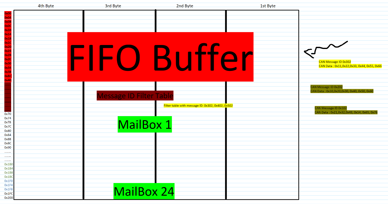
- In the case of reception if external CAN signal’s message ID matches with the ID’s mentioned in Message ID filter table it will copy external CAN data into a memory section of FiFo buffer. So, it works in a FiFo mechanism, First Come first out. Whichever CAN message ID out of Message ID filter table comes first will be read first by MCU.
- In the case of transmission, MCU will copy CAN data from message ID transmit table in configured order (ascending or descending) to the memory section of the FiFo buffer. And Can data be transmitted continuously until whole transmit message ID table is empty.
- In FiFo mechanism, Host MCU configure a section of memory in message buffer as FiFo Buffer. And data reception and transmission will happen from this FiFo buffer only on the basis of First in First Out. Whichever message Id is detected first would be processed first by MCU.
Let’s understand FiFo mechanism from receiving perspective. As FiFo mechanism is mainly for receiving of CAN Data. In this mechanism, we configure which all message ID’s we want to receive in FiFo buffer via Message ID filter Table. If any of the external CAN signal message ID, matches with the message ID of filter table the CAN data is written into the FiFo Buffer.
Host Microcontroller has to read the CAN data from the FIFO buffer memory space. FIFO buffer is x message deep. This x varies in different CAN peripherals and CAN IC’s. It can store up-to x messages in its buffer and HOST MCU can read the data sequentially in the order it is received. If MCU doesn’t read the data, then corresponding error flags would be raised by FiFo engine. Those 2 are watermark and overflow error.
- Watermark error is raised when FIFO buffer is almost full, indicating to HOST MCU that it should read the data from FIFO, FIFO buffer is almost full.
- Overflow error is raised, when FIFO buffer is full and again new CAN data is received by FIFO. When Overflow error is raised, new data will be overwritten by first data that was received and it will be lost. As FIFO buffer is full, so it will start overwriting the new CAN Data.
What is Message ID filter table?
This is a memory space in memory buffer created when we use FIFO mechanism. Over here Host MCU write’s the Message ID’s that should be accepted by FIFO Buffer. Message ID filter table is given a name table, as over here we can list down message IDs according to acceptance criteria type that should be accepted by FIFO Buffer.
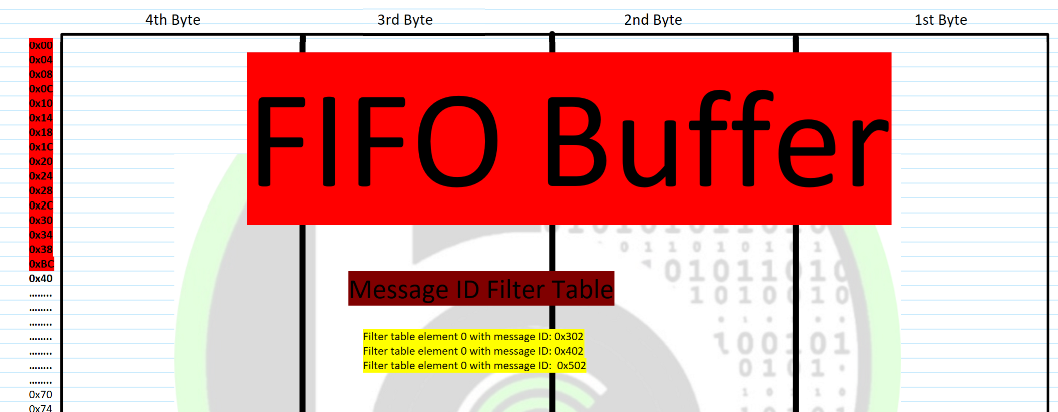
In a single row of the table 1 acceptance criteria is written. So more the number of rows a greater number of message ID’s can be filtered. During Rx FiFo mechanism, CAN messages are received according to Message ID filter table. Only those message ID’s which are mentioned in message ID filter table would be received. All other message ID’s would be discarded from a corresponding CAN node.
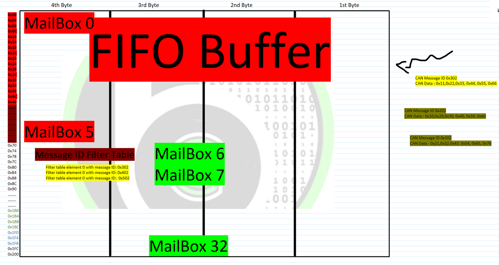
The implementation of message ID filter is also different in SoC to SoC. In some controller’s Message ID filter table is in same memory area of message buffer where mailboxes are present. So in those increasing the Message ID filter table rows, reduces the MailBoxes number available for application. In some SoC, Message ID filter table is at different memory area of message buffer then mailboxes. So, increasing the Message ID filter table rows, doesn’t impact the mailboxes numbers.
What are Acceptance criteria?
Acceptance criteria in CAN is powerful filtering scheme to accept only frames intended for the target application. We can Configure which frames to accept in FIFO mechanism by mentioning the message IDs in the Message ID Filter Table. Message IDs of Standard CAN, Extended CAN or CAN FD, all of these are supported.
Acceptance criteria can be of 3 types:
- Single Acceptance criteria
- Dual Acceptance Criteria
- Range of Message ID criteria
In a single acceptance criterion, we can mention 1 message ID per index of filter table that should be accepted. This is simplest form of acceptance criteria. In Dual Acceptance criteria, we can mention 2 message ID per index of filter table that should be accepted. In range of message ID, we can mention a range of message ID’s that should be accepted.
But different SoC’s can have different formats of acceptance criteria. In some SoC’s we can write up to 2 Standard message ID in one acceptance criteria. Acceptance criteria also have features of bit mast, which makes it possible to configure a range of message ID to be accepted. Main moto of acceptance criteria is to provide a powerful filtering scheme, though its implementation and features can vary from SoC to SoC. Use the acceptance criteria and filter table, we can configure a CAN node to receive number of CAN data based on different message IDs.
Today’s vehicles can contain more than 70 devices, commonly called Electronic Control Units (ECUs) or nodes, that control electrical subsystems. These subsystems control the engine, transmission, powertrain and antilock braking/ABS along with many more. Communication between these subsystems is critical to ensure the reliability and safety demanded in the automotive market. The acceptance criteria feature of Controller Area Network allows ECUs to communicate within a vehicle, with each other by assigning different message IDs. We can assign every ECU with a designated Message ID and then configure other ECUs with this message ID, as a acceptance criteria so as to accept its data.
FIFO Mechanism in CAN Controller achives the Multicast reception, multi master and system wide data consistency features of CAN protocol.


Getting Started with Autosar MCAL Layer
Looking to learn Autosar Software Tech Stack?? Autosar MCAL Layer is the easiest and inexpensive way to start learning your automotive software journey that too with Handson DIY projects and not just theoretical way
Cryptography Do It Yourself (DIY) projects
Learn Cryptography technology in embedded through DIY projects using NXP S32K144 Automotive Chips
How Cryptography in Automotive is implemented.
In the new age of autonomous and connected vehicles, cyber-attacks in automotive are happening frequently. Discover in this blog, what technology is used to make our vehicles safe and secure.
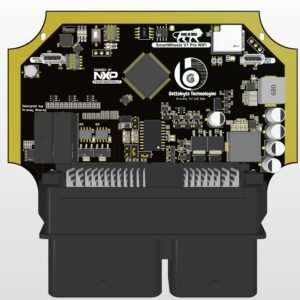
AutoBoardV1 Automotive Board ( HSM Crypto Peripheral +Ethernet)
Low-Cost Automotive Evaluation Board for S32K344
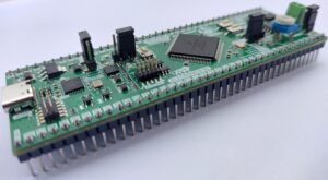
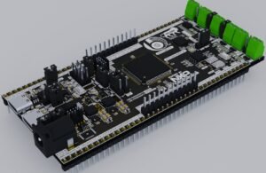
ElecronicsV3 Automotive Board (SHE Crypto Peripheral + CAN)
Low cost Development Board for NXP S32K144 MCU as beginner friendly automotive kits