
So hello guys, welcome back to NXP Semiconductors S32K144 MCU Tutorial series. In the last 2 blogs we had started with S32K144 MCU GPIO Peripheral & UART Peripheral .
In this blog we are going to explore the I2C Peripheral. Going to Start with I2C peripheral. Objective would be to get.
- familiarity with I2C peripheral for S32K144 MCU.
- Would be understanding I2C peripheral from Hardware point of view in S32K144 MCU.
- Going to understand then how to use I2C peripheral via S32K SDK/i2c driver.
- Would also be demonstrating the i2c_echo_pall sketch.
So read along the blog and do tell me its reviews!
I2C Peripheral Theory
I2C Peripheral is a serial communication protocol which are used to interface external sensor and display screens to the Host MCU. Sensors like IMU sensor, Torque sensor, OLED Display screen and etc
To know about I2C peripheral theory, you can refer to this blog.
I2C Peripheral in S32K144 MCU
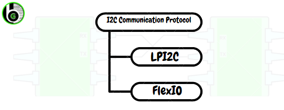
In S32K144 MCU, I2C protocol can be used via 2 peripherals: LPI2C & FlexIO.
LPI2C is referred as Low Power Inter Integrated Circuit. LPI2C is on chip peripheral only to do I2C communication protocol. I2C is a serial protocol which is done via I2C supported peripherals in the Microocntrollers.
Also, in S32K144 there is FlexIO peripheral through which on-board serial communication protocols like UART, I2C & SPI can be emulated. So through FlexIO peripheral, also I2C peripheral can be implemented. To know about FlexIO peripheral in S32K144, refer to this blog.
Features of I2C via LPI2C peripheral in S32K144 MCU:
- LPI2C supports standard-mode, fast -mode , fast-mode plus and ultra -fast modes of operation
- High Speed Mode(HS) in slave mode.
- Multi-master support, including synchronization and arbitration. Multi-master means any number of master nodes can be present.
- Clock stretching support.
- Slave addressing via 7 bit( upto 2^7 slaves can be connected at same I2C lines) and 10 bit(upto 2^10 slaves can be connected at same I2C lines).
- Support of DMA and Interrupts for both I2C master & slave.
- LPI2C also has Support of System Managment Bus Specification, version 2(SMBus), it is used for design of Smart Battery System.
Features of LPI2C master:
- Transmit and Receive FIFO of 4 words.
- Transmit FIFO can initiate START and STOP conditions for starting I2C communication. As I2C master always initiate the communication session.
- Flag and interrupts signal to Start Signals, STOP signals, loss of arbitration, unexpected NACK and command word errors.
Features of LP12C Slave:
- There are registers for configuring address if MCU is used as I2C slave. This is done so as to minimize software overhead because of master/slave switching.
- Software-controllable ACK or NACK.
- Flag and interrupt signals for end of a packet, STOP condition or bit error detection.
How to get started with I2C peripheral in S32K144 MCU
I2C Hardware Pinout in S32K144 MCU
LPI2C Pinout and Hardware Instances
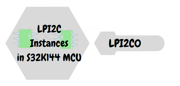
LPI2C peripheral in S32K144 has 1 instance: LPI2I2C0
In S32K MCU, LPI2C peripheral can be used in 4 wire schemes & 2 Wire Scheme. For this blog we are going to focus on 2-wire scheme. To know about 4-wire scheme, refer to this blog.
All The LPI2C Instances has 5pins, instead of traditional 2 pins:
- SCL (Serial Clock): It is used as SCL pin in 2-wire scheme.
- SDA (Serial Data): It is used as SDA pin in 2-wire scheme.
- HREQ (Host Request): If host request is asserted and the I2C bus is idle, then it will initiate an LPI2C master transfer.
- SCLS (Secondary I2C clock line): Not used in 2 wire scheme.
- SDAS (Secondary I2C data line): Not used in 2-wire scheme.
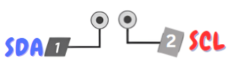
S32K144 I2C Pins
Each LPI2C instance in S32K144 supports all the 2 pins, with below mentioned pin details. Refer to this blog to know about Pins Signal description in S32K144 MCU
In LPI2C0 there are following number of pins:
- For SDA there are 2 MCU pins.
- For SCL there are 2 MCU pins.

LPI2C0 Pins in S32K144
How to do LPI2C Pin Configuration
In a MCU a single pin can work as multiple function, so we have to configure that which function we need, accordingly pins have to be configured. This configuration of Alternate functions of pins in S32K144 MCU is done by Signal Multiplexing peripheral. One can configure which pin to use for LPI2C, via Signal Multiplexing peripheral, in which there is a register Pin Control Register (PCR) which has Pin Mux Control bits(MUX) for configuring the alternate functions of the pins.
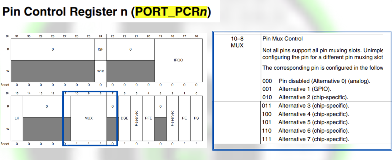
For example, we are using LPI2C0. Now in LPI2C0 for using SCL-SDA pins one can configure PTA3-PTA2 pins:
- You can see SSS column in the excel in that for PTA3 under LPI2C0_SCL has value of 0000_0011. Last 3 bits of this value represents the MUX values to be configured for configuring PTA3 pin as LPI2C0_SCL pin, in PORT_PCRn register.
- You can see SSS column in the excel in that for PTA2 under LPI2C0_SDA has value of 0000_0011. Last 3 bits of this value represents the MUX values to be configured for configuring PTA3 pin as LPI2C0_SDA pin, in PORT_PCRn register.
This part of LPUART pins configuration is done internally by S32 SDK/pin driver (Its detail overview is in GPIO Peripheral in S32K144 MCU). When writing the code, we just need to configure the structure g_pin_InitConfig in which. mux member for the corresponding MCU pin will be assigned value according to last 3 bits of SSS column, as shown below and pass that structure in PINS_DRV_Init().
At line 13 and 26 you see .mux is assigned with PORT_MUX_ALT_3. The value of this is taken from port_mux_t Enum which is defined in pins_driver.h file as follows. The members defined in this Enum is according to the MUX bits values defined in PCRn register. So according to the value of the last 3 bits of SSS column, we will configure the. mux member of g_pin_InitConfig structure.
I2C SDK for S32K144 MCU
LPUART SDK
S32K SDK/drivers provide an easy to use and quick way to use the LPI2C peripheral in S32K144, which is known as LPI2C SDK.
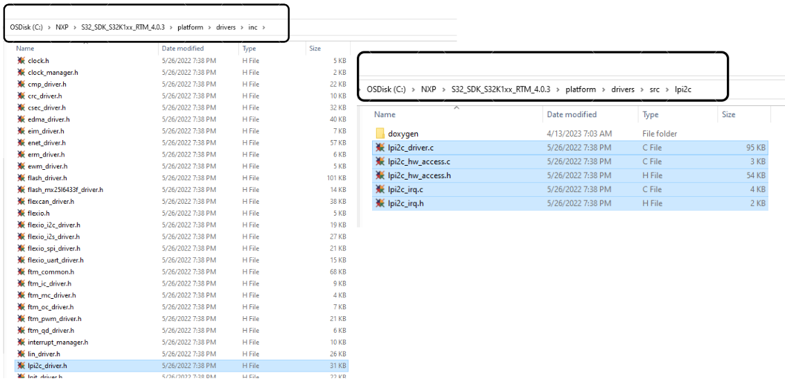
Each S32 SDK driver can be configured and enabled to use in the project via S32 Configuration Tool. Will be digging into that part, in next section. For now, let’s understand the LPI2C SDK in some detail, so as to use I2C peripheral via LPI2C.
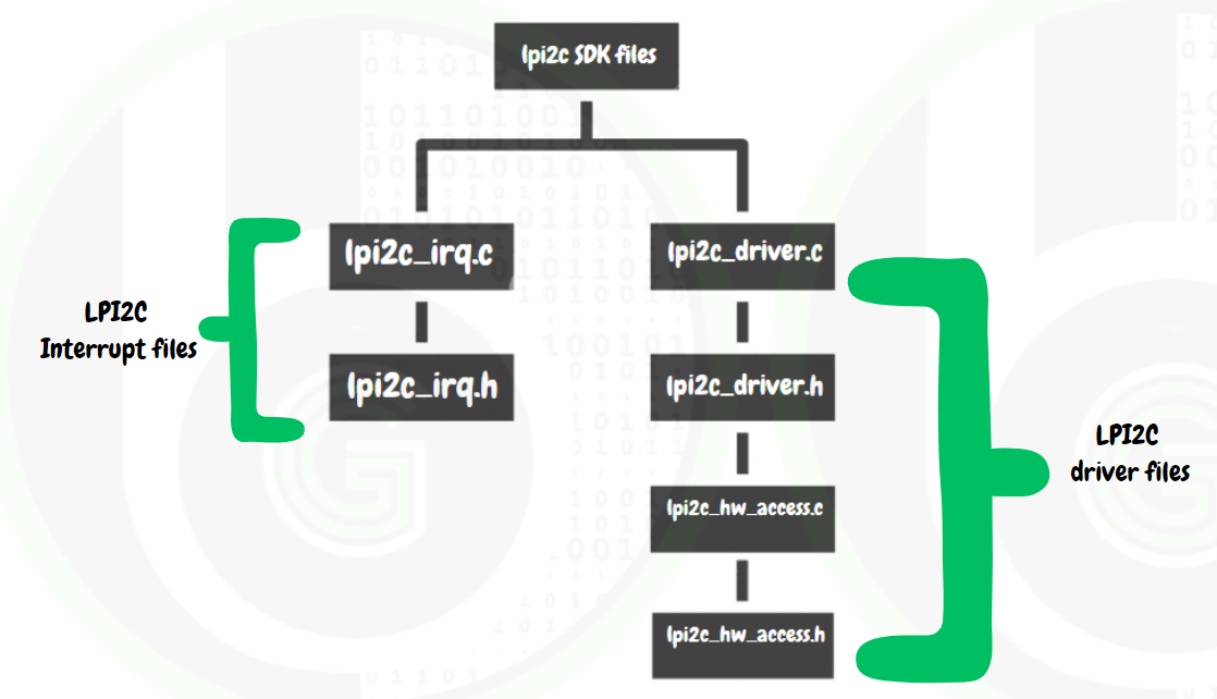
In the SDK of LPI2C there are header and source files for LPI2C Driver and LPI2C Interrupt
- LPUART interrupt files contains functions for using &configuring of LPUART interrupts and IRQ handler in S32K144 MCU.
- LPUART driver files contains functions for using/configuration of LPUART Peripheral.
LPI2C Driver
LPI2C driver files are further divided into LPI2C Peripheral Abstraction Layer(PAL) & LPI2C Low Level drivers, as shown below:
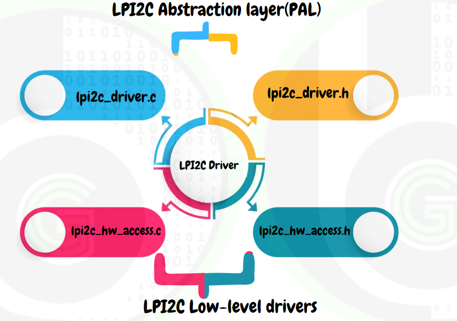
- LPI2C Peripheral Abstraction Layer(PAL): contains functions and variables that are directly used in main.c or application code. And internally these functions use the LPI2C Low-level drivers & LPI2C IRQ. So if hardware is changed LPI2C PAL would remain same and only internal low-level driver files need to be changed or modified. By this way we don’t have make many changes on application level.
- LPI2C Low-level driver: contains functions that configures the LPI2C peripheral registers for initializing the peripheral, using the peripheral and processing the data of peripheral at hardware level. These files are the ones which actually interacts with the hardware and make it configurable to our needs. 
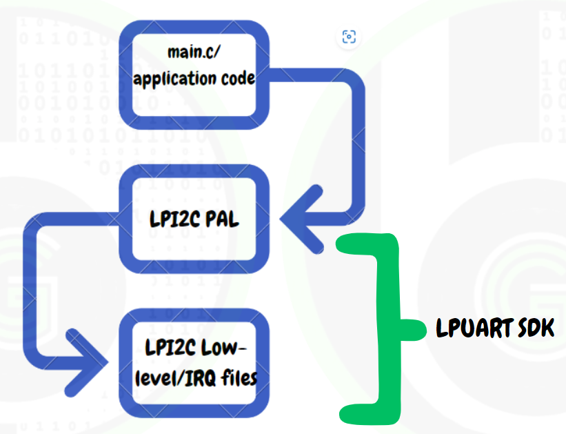
LPI2C PAL
In LPI2C PAL there are 2 files lpi2c_driver.c and lpi2c_driver.h files.
Let’s get into these files:
- lpi2c_driver.h: contains the Enum’s, structures and function declarations that would be used in application code. Only functions which are declared in this header file can be used in main.c or application project.
lpi2c_driver.c: contains the function definitions of the declared functions (uses the low-level driver functions) along with some static functions also that are restricted to use in this file only.
Functions
LPI2C Master Functions
- LPI2C_DRV_MasterInit: This function is first function to be used in main.c or application code to initialize the I2C peripheral in Master Mode.
This function has 3 function parameters as follows:
- instance: integer number indicating which instance of LPUART we are going to use.
- userConfigPtr: Structure pointer have to be sent for lpii2c_master_user_config_t structure
- master: Structure pointer have to be sent for lpi2c_master_state_t structure.
- LPI2C_DRV_MasterSendData: This function starts the transmission of a block of data to the currently configured slave address via non-blocking method. The transmission of data via this API is handled by the Interrupt Service Routine. That is this function returns immediately and we need to call LPI2C_DRV_MasterGetSendStatus() to check the progress of the transmission.
This function has 4 function parameters:
- instance: integer number indicating which instance of LPUART we are going to use.
- txBuff: buffer pointer, pointing to the data which needs to be send out.
- txSize: size of data that has to be sent.
- sendStop: specifies whether to generate the stop condition after the transmission.
- LPI2C_DRV_MasterSendDataBlocking: This function
This function has 5 function parameters:
- instance: integer number indicating which instance of LPUART we are going to use.
- txBuff: buffer pointer, pointing to the data which needs to be send out.
- txSize: size of data that has to be sent.
- sendStop: specifies whether to generate the stop condition after the transmission
- timeout:timeout values in miliseconds
- LPI2C_DRV_MasterReceiveData:
This function has 4 function parameters:
- instance: integer number indicating which instance of LPUART we are going to use.
- rxBuff: buffer pointer, pointing to the buffer where to store received data.
- txSize: size of data that has to be sent.
- sendStop: specifies whether to generate the stop condition after the transmission
- LPI2C_DRV_MasterReceiveDataBlocking:
This function has 5 function parameters:
- instance: integer number indicating which instance of LPUART we are going to use.
- rxBuff: buffer pointer, pointing to the buffer where to store received data.
- txSize: size of data that has to be sent.
- sendStop: specifies whether to generate the stop condition after the transmission
- timeout:timeout values in miliseconds
- LPI2C_DRV_MasterIRQHandler:
LPI2C Master Data Types
Their are 2 structures that are important and will be used:
- lpi2c_master_user_config_t: This structure has members to configure the LPI2C according to user defined settings.
- lpi2c_master_state_t: This structure has data members, which keep track of the on-going transfers .
LPI2C Slave Functions
- LPI2C_DRV_SlaveInit: This function is first function to be used in main.c or application code to initialize the I2C peripheral in Slave Mode
This function has 3 function parameters as follows:
- instance: integer number indicating which instance of LPUART we are going to use.
- userConfigPtr: Structure pointer have to be sent for lpii2c_slave_user_config_t structure
- master: Structure pointer have to be sent for lpi2c_slave_state_t structure.
- LPI2C_DRV_SlaveSendData:
This function has 3 function parameters:
- instance: integer number indicating which instance of LPI2C we are going to use.
- txBuff: buffer pointer, pointing to the data which needs to be send out.
- txSize: size of data that has to be sent.
- LPI2C_DRV_SlaveSendDataBlocking:
This function has 3 function parameters:
- instance: integer number indicating which instance of LPI2C we are going to use.
- txBuff: buffer pointer, pointing to the data which needs to be send out.
- txSize: size of data that has to be sent.
- timeout:timeout values in miliseconds.
- LPI2C_DRV_SlaveReceiveData:
This function has 3 function parameters:
- instance: integer number indicating which instance of LPI2C we are going to use.
- rxBuff: buffer pointer, pointing to the buffer where to store received data
- rxSize: size of data that has to be received.
- LPI2C_DRV_SlaveReceiveDataBlocking:
This function has 4 function parameters:
- instance: integer number indicating which instance of LPI2C we are going to use.
- rxBuff: buffer pointer, pointing to the buffer where to store received data
- rxSize: size of data that has to be received.
- timeout:timeout values in miliseconds.
- LPI2C_DRV_SlaveIRQHandler:
LPI2C Slave Data Types
Their are 2 structure that are important and will be often used
I2C Demo Code for S32K144 MCU
Lorem ipsum dolor sit amet, consectetur adipiscing elit. Ut elit tellus, luctus nec ullamcorper mattis, pulvinar dapibus leo.