DIY Projects

How to do CAN Communication using Automotive Microcontroller S32K144 via ElecronicsV3(Non-Autosar Driver)

Table of Contents

Introduction to CAN

So we have started the DIY project series on Automotive Microcontroller S32K144, using the ElecronicsV3 Development board to understand the automotive peripherals and protocols. In this blog, we are going to delve into the CAN Communication protocol hands-on. We are going to do a CAN communication basic DIY hands-on project to transmit and receive Standard CAN messages. Now let’s dwell on this journey!!!

Communication

What is CAN communication?

CAN, or Controller Area Network, is one of the robust vehicle bus standards communication protocols designed to allow ECUs of a car to communicate with each other. Think of it as a language via which ECUs of car of different domains like: Body Control Domain, Chassis Domain and etc. use to talk to each other. Before CAN the wire system in a vehicle is very messy and costly because of large number of wires used in vehicle to connect different domains, but because of CAN we can connect multiple ECU via only 2 wires so as to have simple wireinh and reduce the cost.

To know more about what CAN technology and its overview is, refer to this blog and video. In this blog, we have set our focus to dwell into Handson activities and knowledge to do CAN communication practically. Theoretical and general overview content is very easily available over net, but practical knowledge is what lacks the most.

Reason for diving in CAN

Why Did I Dive into CAN?

I’ve always been fascinated by seamless system communication, like sensors in cars or home automation. Understanding CAN is crucial due to its widespread use and robust data handling. CAN reduces wiring complexity by using a single pair of twisted wires, ensures data integrity through error detection, prioritizes messages via arbitration, and supports broadcast communication. This makes it more efficient and reliable than traditional protocols, ideal for real-time systems.

CAN node

What is CAN Node?

A CAN (Controller Area Network) node is a device connected to a CAN network that can send and receive messages. Each node includes a microcontroller with a CAN controller and a CAN transceiver.

The Microcontroller controls the CAN Communication, CAN controller manages message framing and protocol handling, while the CAN transceiver converts between the CAN controller’s logic levels and the differential signal on the CAN bus.

About CAN(Controller Area Network) Technology
About CAN Technology
CAN Controllers in Embedded
FlexCAN Peripheral of S32K144 MCU
ElecronicsV3 Board for doing CAN Communication
CAN DIY projects in detail course

DIY Problem Statement

What we’ll follow and do in this project is, serial communication between Electronics V3 and our host computer through CAN protocol. We will be doing basic 2-way CAN Communication between a Microcontroller board(in our case ElecronicsV3) and Desktop.

Nature of CAN Data communication is going to be Standard CAN protocol and operating at 500 kbps baudrate. We are going to transmit CAN data Frame and use different CAN controller mechanisms like Mailbox- RxFIFO to transmit and receive the CAN messages. We are going to use different features of these mechanisms like Tx_MailBox, Rx_MailBox, RxFIFO via different Message ID table’s and acceptance criteria formats. 

We are going to do this DIY problem statement with 2 CAN nodes. One would be S32K144 MCU, for that we will be using its development board ElecronicsV3. And another CAN node would be CAN analyzer tool, that would be Innomaker CAN analyzer. From ElecronicsV3 CAN data communication is done via CAN peripheral of the automotive MCU S32K144. The CAN peripheral is FlexCAN peripheral. This data can be seen through USB to CAN Innomaker device where we can spot various details of transmitted data like Data, CAN ID, Data Length, etc. 

Embedded Hardware Tools to procure for doing this Project:

  1. ElecronicsV3 Board: Automotive MCU S32K144 based cost effective development board.
  2. Innomaker CAN analyzer tool: USB2CAN analyzer tool to transmit/receive/analyze and debug CAN signals via Desktop. 
  3. Jumper Wires(Optional): If you already have jumper wires then no need to buy separately.
  4. Pocket Screw Driver(Optional): For attaching Jumper wires into CAN Screw terminals of ElecronicsV3 board and Innomaker Hardware tool, we would be needing a screw driver. One can also try with knife, but be careful dont harm yourself or others with it.

Embedded Tools Required

Embedded Hardware Tools

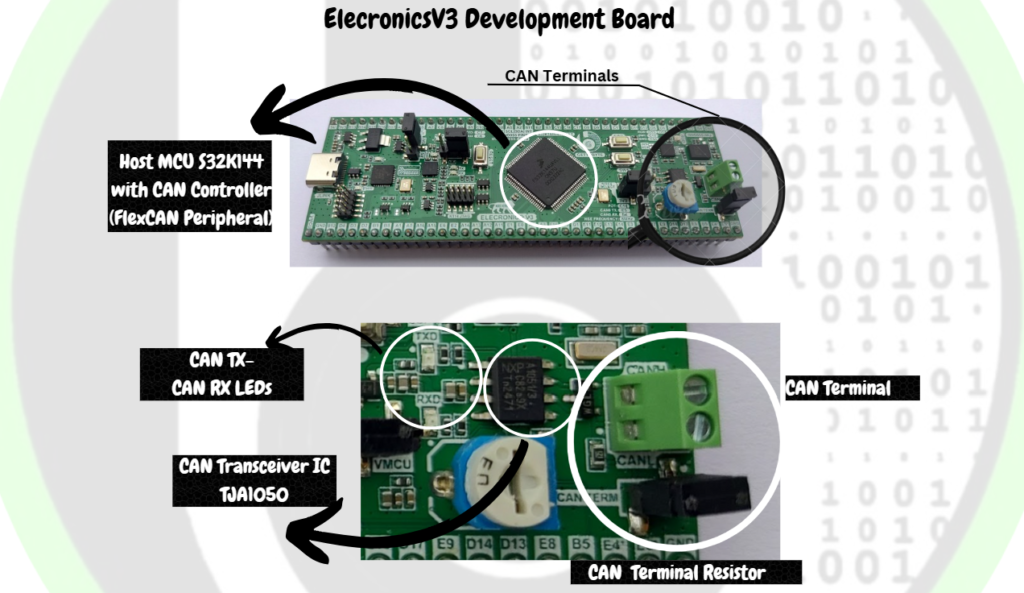
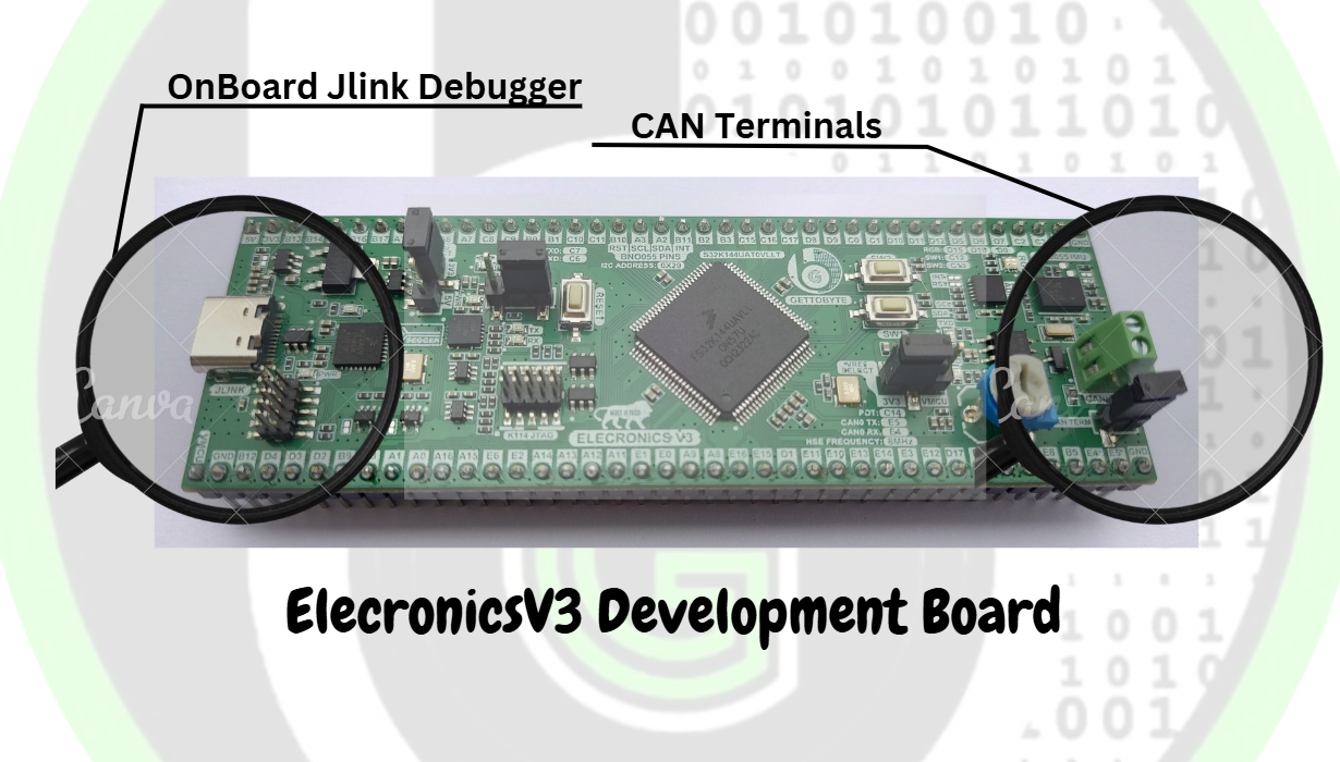
Elecronics V3 is a versatile development board based on the NXP Semiconductor S32K144 MCU. It has On-board 1*CAN channel which supports up to CAN FD protocol. Also, ElecronicsV3 has onboard Jlink Debugger to program and debug the board through Type C USB cable. Making it easy to use and hassle-free enablement to learn CAN technology. To know more about ElecronicsV3 Board, refer this page.

ElecronicsV3_Board_CAN_terminal

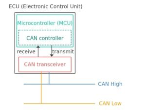
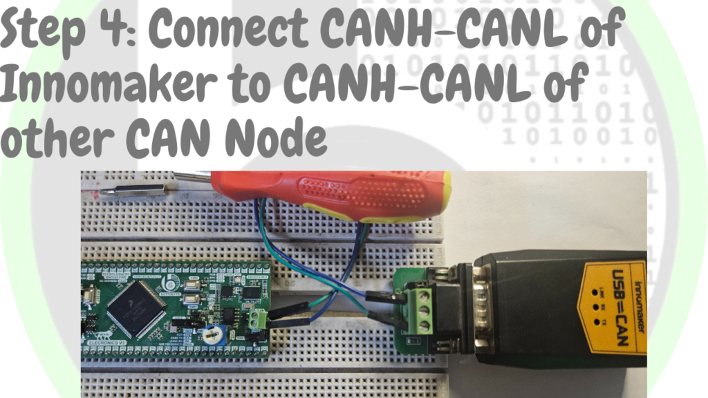
ElecronicsV3 is a complete CAN node, it has on Board Host MCU supporting CAN controller (S32K144 MCU with FlexCAN peripheral) and CAN Transceiver IC(TJA105) connected to CAN Instance 0 through PTE4(CAN-Tx) and PTE5(CAN-Rx) pins of Host MCU. And Via Green Screw terminals CAN Communication pins CAN_H and CAN_L are exposed for external node connection.

ElecronicsV3_Board_CAN_Labelling

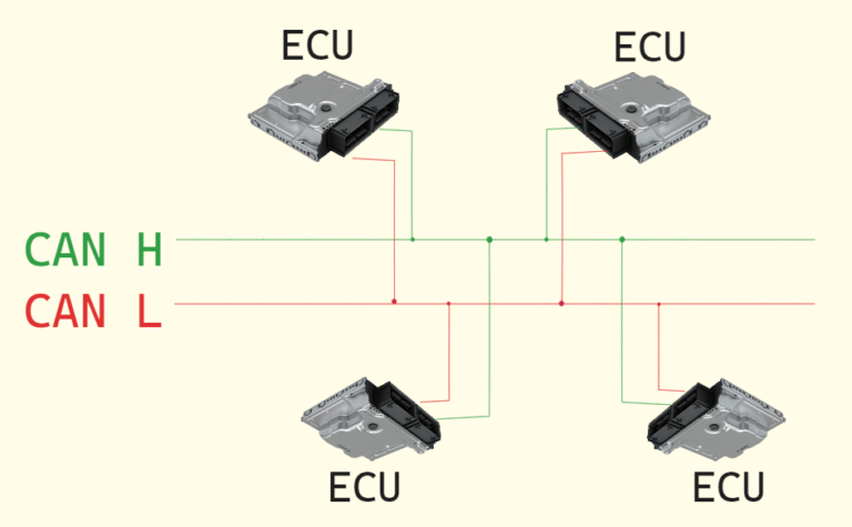
The green screw terminals, which are present on ElecronicsV3 Board would be used to connect with Other CAN nodes. In this case we will connect ElecronicsV3 green Screw terminals with Innomaker CAN analyzer tool.

ElecronicsV3_CAN_Terminal_Connection

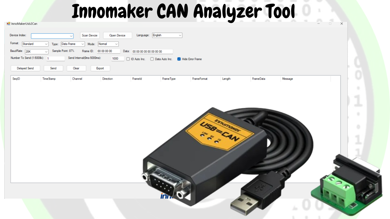
We will be using CAN analyzer tool, for evaluating of CAN messages in the Desktop.  It would be used to transmit and receive the CAN messages from the desktop/PC/Laptop to the CAN Node.

It is a great and must have tool while working with CAN protocol to analyzer/monitor/debug the CAN messages. CAN analyzer tool act as a bridge to communicate between a CAN Node and Desktop via CAN protocol. While learning CAN protocol and doing Handson practical projects, having a CAN Analyzer tool is must and important electronic tool to procure which will help learners to study and capture CAN messages easily.

How to use the CAN Analzyer tool?

To use the CAN Analyzer tool, there would be 2 things. CAN Analyzer Hardware tool and CAN Analyzer Software application.

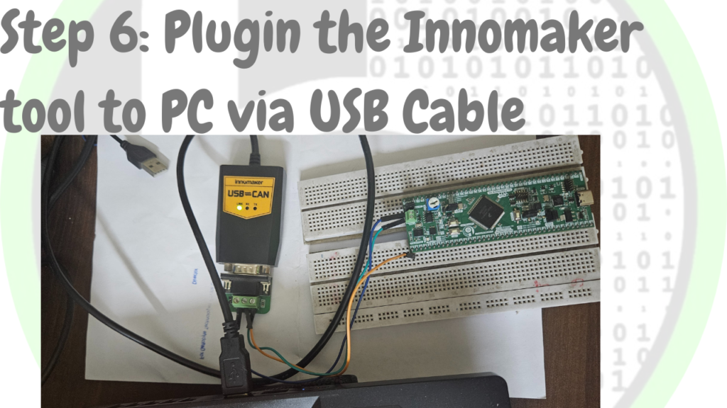
  1. CAN Hardware tool would be used to physically connect with the CAN Node through CAN_H-CAN_L pins and with the Host PC through USB cable.
  2. CAN Software application would be used to see and analyze the CAN messages on the Desktop
Which CAN analyzer tool to use?

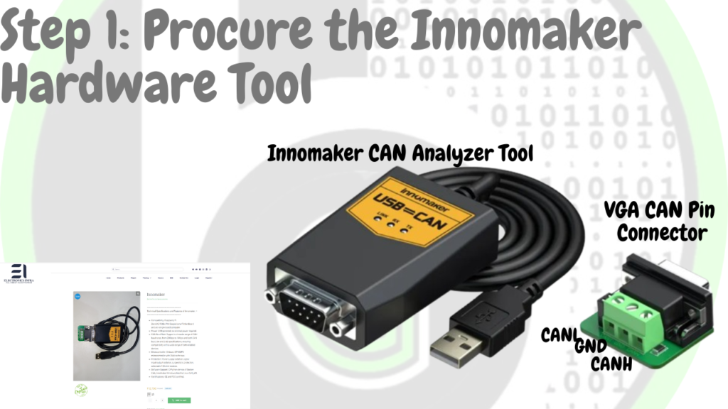
There are many CAN analyzer tools available, but they are quite expensive the industrial grade CAN analyzer tools like that of Vector, Peak and etc starts from 30-40K minimum. So, we are going to use Innomaker CAN Analyzer tool which is cost effective as compared to other tools(Comes at 6-7K) and also very easy to use. Buy Link of Innomaker Hardware tool is here.

Innomaker CAN Analyzer Tool
Connections of Innomaker CAN analyzer tool!

To use the Innomaker CAN Analyzer tool, we would be needing Innomaker Hardware and Innomaker software( This is covered in next section)

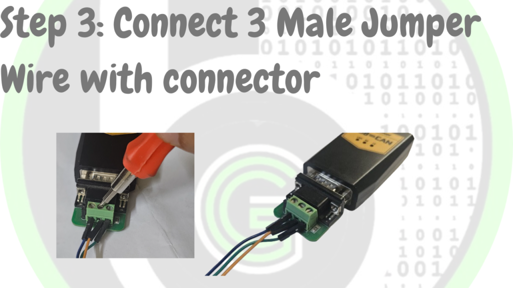
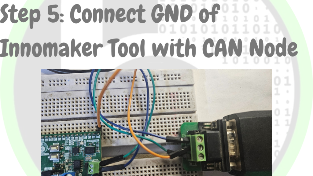
CAN Innomaker Hardware tool connections: When you receive the Innomaker hardware tool, there would be 2 parts in it Innomaker hardware tool and VGA CAN Pins connector.  Just connect these 2 and attach male to male jumper wire on its screw terminals. And then connect these Jumper wires to the CAN pins of the CAN node.

Embedded Software Tools

  • S32Design Studio IDE

S32 Design Studio: S32 Design Studio is the Desktop Application that is used for the development of Embedded Software on the S32 family of Microcontrollers. As ElecronicsV3 has S32K144 Microcontroller, so for writing embedded software programs on S32K144 MCU we will be needing S32DS and thus ElecronicsV3 Board is end to end supported on S32 Design Studio.

Desktop Application which is used to write/program/debug the Embedded Software codes for a microcontroller is called IDE (Integrated Development Environment). Thus S32 Design Studio is an IDE and it is based on Eclipse IDE over which NXP Semiconductor has developed custom plugins to make it use for its S32 Family of MCU’s. 

S32 Design Studio supports GNU GCC compiler, GDB & OpenOCD debugging servers, Segger Jlink & PEMicro Hardware Debuggers. It also comes with Code Configuration Tool, which makes it very handy to develop applications on S32Family of MCU with much of a hassle. To know more about S32 Design Studio refer this blog.

For Installing S32 Design Studio, follow the steps from this link. Over here all steps in detail are explained.

  • S32 RTD Package

To use microcontroller peripherals there is a software stack which is needed, that is termed as Real Time Drivers (RTD). As we are using ElecronicsV3 Development Board which has S32K144 Microcontroller on it. So we will be needing RTD of S32K144 MCU. NXP Semiconductor itself provides RTD for S32K144 MCU. We are going to use Autosar MCAL layer based S32K1 RTD 1.0.0, which is termed as SW32K1_S32M24x_RTD_4.4_R21-11_1.0.0_D2108.

To know more about Real Time Drivers and Its technical in-depth understanding in microcontroller world, refer to this blog.

The stated RTD package above would be having library files(.c/.h files) so as to use all the peripherals of the S32K144 MCU. In this Blog, we are going to focus on FlexCAN peripheral library, which is used for CAN peripheral of the S32K144 MCU. Their are 2 RTD packages in the above stated RTD stack. One is Autosar MCAL layer complaint RTD and one is Non Autosar MCAL layer complaint RTD. In this blog, we are going to use and focus on Non Autosar MCAL layer RTD.

To know about what is Autosar, MCAL layer and Autosar technology, refer to this blog.

Our ultimate goal is to understand the Autosar MCAL layer RTD in order to start the learning for the Autosar Technology stack. However, it is important to note that the RTD of Autosar MCAL layer is dependent on Non-Autosar RTD. To ensure a solid foundation and a clear understanding, it is recommended to begin with the Non-Autosar MCAL layer RTD package before moving on to the Autosar MCAL layer RTD. This approach will help establish a chronological order and enhance comprehension from the ground up.

This RTD can be downloaded from NXP Website and further it can be integrated into S32 Design Studio IDE to use the RTD package while writing the Embedded Software Code for S32K144 MCU. Installation steps of RTD package and how to integrate it into S32 Design Studio have been stated step by step in this blog. Refer this link to know about it.

  • USB2CAN innomaker Desktop Application

CAN Innomaker Software application installation: To analyze and see the CAN messages, we will use Innomaker USB2CAN Desktop Application. That can be downloaded as mentioned in below steps and configurations should be then as stated.

Step 1
Search on google for USB-To-CAN Software and click on GitHub repo link of tool
Click Here
Step 5
Extract the Zip File and run the installer to download software
Click Here
Step 6
Open The Innomaker Software Tool
Click Here
Step 7
Firstly, click on "Scan device" to determine your innomaker then click "Open Device" and configure Baudrate to 500K. All Set.
Click Here
Previous slide
Next slide

So that’s all things which we would be needing for Doing the Stated DIY project statement. Hope so you have procured the Necessary Embedded Hardware Tools from the stated buy links and Installed the Embedded Software application as told in respective sections of tools.

Getting Started

After arranging all the prerequisites, we are going to move toward the Embedded software understanding of data transmission and reception using CAN peripheral, according to our DIY project statement. Make sure to follow the steps keenly and if any suggestion is invoked, please submit it on our community forum.

Step 1: Cloning the Repo from our GettoByte Github

Download the ElecronicsV board Demo codes from the GitHub Repo of Gettobyte Technologies. If you have installed the Git, then one can clone the repo. Otherwise, one can download the repo by its zip file.

For cloning the repo, you can directly download it as a .zip file and extract it, else you can also use Tortoise Git to extract the files.

GitHub Link for Demo Code

Step 2: Opening the cloned repo in S32 Design Studio

After getting the repo, now we are going to open the GitHub repo Example projects in S32 Design Studio. Make sure that you have downloaded the S32 Design Studio 3.4 and S32K1 RTD package version which we have stated in tools installation.

Follow the below steps mentioned in slider to Open the Example projects in S32 Design Studio.

Step 1
Click on File tab on top-left of S32 DS(Design Studio) and go to Open projects from File System
Step 2
Click on "Directory" button for accessing your storage and locate your folder to opened. In our case, it is the folder that is downloaded and extracted from GitHub Repo.
Click Here
Step 3
You can also extract complete folder to S32 DS but it is recommended to extract to only use that folder which are completely build and requires no changes.
Click Here
Step 4
Locating to CAN module only for focused working.
Click Here
Step 5
CAN folder is located and click on "Select Folder"
Click Here
Step 6
Click on "Finish" button and you have successfully imported the GitHub Repo.
Click Here
Previous slide
Next slide

Step 3: Building the specific code out of multiple examples

After opening the Example projects in S32 Design Studio. You will be able to see list of Example projects in your project explorer window. Each project naming has been done in a way that one can get to know what feature of FlexCAN peripheral of S32K144 MCU we are going to test. In all of these example projects we are using Standard CAN message in Normal Mode at 500 kbps baudrate.

Explore the different example projects, as per your understanding. Their are 6 example projects. In these example project focus is towards the understanding of MailBox and RxFIFO mechanisms and concepts of CAN controller. For those who dont know about these, its good to have understanding about these concepts at first. Users can read this blog, in which in detail technical understanding is given about CAN controllers concepts for doing CAN communication.

  1. GB_FlexCAN_MailBox_Int_ElecronicsV2_S32K144: Example projects for doing CAN communication (transmission and reception) via mailbox mechanism using Interrupt method.
  2. GB_FlexCAN_MailBox_Polling_ElecronicsV2_S32K144: Example projects for doing CAN communication (transmission and reception) via mailbox mechanism using polling method.
  3. GB_FlexCAN_MailBox_RxFiFo_ElecronicsV2_S32K144: Example project for doing CAN communication(transmission and reception) via MailBox and RxFIFO mechanism using interrupt method.
  4. GB_FlexCAN_Rx_FIFO_DMA_ElecronicsV2_S32K144: Example project for doing CAN reception via RxFIFO mechanism using DMA method.
  5. GB_FlexCAN_Rx_FIFO_Int_ElecronicsV2_S32K144: Example project for doing CAN reception via RxFIFO mechanism using Interrupt method.
  6. GB_FlexCAN_Rx_FIFO_Polling_ElecronicsV2_S32K144: Example projects for doing CAN reception via RxFIFO mechanism using Polling method.

Follow the below 3 steps to open the example projects in S32 Design Studio. In step 3, users will also find the description of each example project. Note: Example projects are named with ElecronicsV2, but example are applicable to ElecronicsV3 also.

Step 1
Preview of Folder in "Project Folder" tab in S32 DS
Step 2
This is how your project will look when you'll open your project. Different subfolder contains different files and configuration to your project. Your focus should be on "src" which will contain source code to be debug and run.
Step 3
Right clicking on project folder will open dialog box where you can see option "Build Configuration" which is used to configure different sub-project in your project.
Step 4
After selecting project and its build configuration to use. Build the example project.
Click Here
Step 5
After Clicking on Build project your project will start compiling, if all things goes well.
Click Here
Previous slide
Next slide

Viwers can also refer this video, if they have any issues in above steps. Or they can post their queries at gettobyte community forum if they get stuck.

Now lets run and understand the example projects one by one.We are not going to dwell into all example projects in this blog, we are going to focus on 3 example projects. After understanding these three-example project, rest 3 example projects can be understood on their own:

  1. GB_FlexCAN_MailBox_Int_ElecronicsV2_S32K144: Example projects for doing CAN communication (transmission and reception) via mailbox mechanism using Interrupt method.
  2. GB_FlexCAN_MailBox_RxFiFo_ElecronicsV2_S32K144: Example project for doing CAN communication(transmission and reception) via MailBox and RxFIFO mechanism using interrupt method.
  3. GB_FlexCAN_Rx_FIFO_Int_ElecronicsV2_S32K144: Example project for doing CAN reception via RxFIFO mechanism using Interrupt method

GB_FlexCAN_MailBox_Int_ElecronicsV2_S32K144

  1. Demo Example project description
  2. Code Configuration Tool explanation
  3. main.c explanation for both the examples
  4. flashing the example project and opening in debug perspective and telling where all breakpoints to set
  5. seeing the final output.

GB_FlexCAN_MailBox_RxFiFo_ElecronicsV2_S32K144:

  1. Demo Example project description
  2. Code Configuration Tool explanation
  3. main.c explanation for both the examples
  4. flashing the example project and opening in debug perspective and telling where all breakpoints to set
  5. seeing the final output.

GB_FlexCAN_Rx_FIFO_Int_ElecronicsV2_S32K144:

  1. Demo Example project description
  2. Code Configuration Tool explanation
  3. main.c explanation for both the examples
  4. flashing the example project and opening in debug perspective and telling where all breakpoints to set
  5. seeing the final output.

Code Explanation

Transmitting Data Using MailBox Interrupts

example1.c
C++
#include "Mcal.h"
#include "Clock_Ip.h"
#include "FlexCAN_Ip.h"
#include "Port.h"
#include "IntCtrl_Ip.h"

extern void CAN0_ORED_0_15_MB_IRQHandler(void);

#define MSG_ID 800u
#define TX_MB_IDX 10

uint8 dummyData[8] = {1,2,3,4,5,6,7};

void TestDelay(uint32 delay)
{
   static volatile uint32 DelayTimer = 0;
   while(DelayTimer<delay)
   {
       DelayTimer++;
   }
   DelayTimer=0;
}

int main(void)
{
    Flexcan_Ip_StatusType FlexCAN_Api_Status;

    Clock_Ip_Init(&Mcu_aClockConfigPB[0]);
#if defined (FEATURE_CLOCK_IP_HAS_SPLL_CLK)
    while ( CLOCK_IP_PLL_LOCKED != Clock_Ip_GetPllStatus() )
    {
        /* Busy wait until the System PLL is locked */
    }
    Clock_Ip_DistributePll();
#endif

    IntCtrl_Ip_EnableIrq(CAN0_ORed_0_15_MB_IRQn);
    IntCtrl_Ip_InstallHandler(CAN0_ORed_0_15_MB_IRQn, CAN0_ORED_0_15_MB_IRQHandler, NULL_PTR);

    Port_Init(NULL_PTR);

    Flexcan_Ip_DataInfoType rx_info = {
            .msg_id_type = FLEXCAN_MSG_ID_STD,
            .data_length = 8u,
            .is_polling = FALSE,
            .is_remote = FALSE
    };

    FlexCAN_Ip_Init(INST_FLEXCAN_0, &FlexCAN_State0, &FlexCAN_Config0);

    FlexCAN_Api_Status = FlexCAN_Ip_SetStartMode(INST_FLEXCAN_0);

   for(;;)
   {
       FlexCAN_Api_Status = FlexCAN_Ip_Send(INST_FLEXCAN_0, TX_MB_IDX, &rx_info, MSG_ID, (uint8 *)&dummyData);
       TestDelay(2000000);
   }

    return 0;
}

Breaking Down the Code

  • Initialization:

    Clock_Ip_Init(&Mcu_aClockConfigPB[0]);

    Initializes the system clock. Ensures the microcontroller operates at the desired frequency.

  • Interrupt Handling:

    IntCtrl_Ip_EnableIrq(CAN0_ORed_0_15_MB_IRQn);
    IntCtrl_Ip_InstallHandler(CAN0_ORed_0_15_MB_IRQn, CAN0_ORED_0_15_MB_IRQHandler, NULL_PTR);
     
    Enables the interrupt and installs the handler for the CAN0 interrupts. This ensures that when an interrupt occurs, the CAN0_ORED_0_15_MB_IRQHandler the function is called.
  • Port Initialization:

    Port_Init(NULL_PTR);

    Initializes the pins used by the CAN module. This step is crucial to ensure that the CAN communication pines are properly configured.

  • CAN Initialization:

    FlexCAN_Ip_Init(INST_FLEXCAN_0, &FlexCAN_State0, &FlexCAN_Config0);

    Initializes the CAN module with the specified configuration. This prepares the FlexCAN module of S32K144 MCU for communication.

  • Sending Data:

    FlexCAN_Api_Status = FlexCAN_Ip_Send(INST_FLEXCAN_0, TX_MB_IDX, &rx_info, MSG_ID, (uint8 *)&dummyData);

    Sends data using the specified mailbox. The TX_MB_IDX defines which mailbox is used for transmission, and dummyData is the data being sent.

Receiving Data Using MailBox Interrupts

example2.c
Objective-C
#include "Mcal.h"
#include "Clock_Ip.h"
#include "FlexCAN_Ip.h"
#include "Port.h"
#include "string.h"
#include "IntCtrl_Ip.h"

extern void CAN0_ORED_0_15_MB_IRQHandler(void);

#define MSG_ID 800u
#define RX_MB_IDX 0U

GB_MailBox_CallBack(uint8 instance, Flexcan_Ip_EventType eventType,
                  uint32 buffIdx, const Flexcan_Ip_StateType * flexcanState)
{
#if GB_RxMailBox_CALLBACK
	Flexcan_Ip_StateType * state = flexcanState;
	state->mbs[buffIdx].state = FLEXCAN_MB_RX_BUSY;
#else

	uint8_t callback = 0;
	/* Do Nothing */
#endif
}

int main(void)
{
    Flexcan_Ip_StatusType FlexCAN_Api_Status;

    Clock_Ip_Init(&Mcu_aClockConfigPB[0]);
#if defined (FEATURE_CLOCK_IP_HAS_SPLL_CLK)
    while ( CLOCK_IP_PLL_LOCKED != Clock_Ip_GetPllStatus() )
    {
        /* Busy wait until the System PLL is locked */
    }
    Clock_Ip_DistributePll();
#endif

    IntCtrl_Ip_EnableIrq(CAN0_ORed_0_15_MB_IRQn);
    IntCtrl_Ip_InstallHandler(CAN0_ORed_0_15_MB_IRQn, CAN0_ORED_0_15_MB_IRQHandler, NULL_PTR);

    Port_Init(NULL_PTR);

    Flexcan_Ip_DataInfoType rx_info = {
            .msg_id_type = FLEXCAN_MSG_ID_STD,
            .data_length = 8u,
            .is_polling = FALSE,
            .is_remote = FALSE
    };
    Flexcan_Ip_MsgBuffType rxData;

    FlexCAN_Ip_Init(INST_FLEXCAN_0, &FlexCAN_State0, &FlexCAN_Config0);

    FlexCAN_Api_Status = FlexCAN_Ip_SetStartMode(INST_FLEXCAN_0);
    FlexCAN_Api_Status = FlexCAN_Ip_ConfigRxMb(INST_FLEXCAN_0, RX_MB_IDX, &rx_info, MSG_ID);

    FlexCAN_Api_Status = FlexCAN_Ip_Receive(INST_FLEXCAN_0, RX_MB_IDX, &rxData, false);

   for(;;)
   {
       // Infinite loop to keep the program running
   }

    return 0;
}

Breaking Down the Code

  • Callback Function:

    GB_MailBox_CallBack(uint8 instance, Flexcan_Ip_EventType eventType, uint32 buffIdx, const Flexcan_Ip_StateType * flexcanState)


    This function handles the received messages. When a message is received, this function updates the state of the mailbox.

  • Configuring the Mailbox:

    FlexCAN_Api_Status = FlexCAN_Ip_ConfigRxMb(INST_FLEXCAN_0, RX_MB_IDX, &rx_info, MSG_ID);


    Configures the mailbox for receiving messages. The RX_MB_IDX specifies the mailbox index and MSG_ID specifies the message ID to filter.

  • Receiving Data:

    FlexCAN_Api_Status = FlexCAN_Ip_Receive(INST_FLEXCAN_0, RX_MB_IDX, &rxData, false);


    Receives data using the specified mailbox. The rxData buffer stores the received data.

DIY Course on CAN Technology

To understand nitty gritty details of the Demo codes and how to run the demo codes so as to see the desired output. Enroll the course on ” CAN Protocol Handson Using Automotive MCU”. 

In the Course we have taught above stated demo examples with in detail code explanation, code configuration tool generation, how to debug and see the desired output, Important API’s of FlexCAN module which are used for doing CAN communication.

This course is perfect blend of theoritical knowledge with practical learning to make users aware about nitty gritty details and important concepts of CAN controllers which plays very important part to use CAN technology, but hardly people knows about.

CAN_Course_HAndson

The course is priced at INR 2053. The course content is rare to find and covers niche topics of CAN Technology. To know more about this course, explore the course page at edu.gettobyte.com.

Conclusion

Now, you have successfully learned, how to transmit or receive data using Standard CAN on Elecronics V3 via the MailBox mechanism through interrupt and polling methods. For more learning, you can refer to more blogs. But for more precise learning on CAN, you can go through our complete course on Communication with CAN.

Rohan Singhal
Author: Rohan Singhal

Author

Rohan Singhal

Leave a comment

Stay Updated With Us

Error: Contact form not found.

      Blog