UART Channels and Pair of Pins
–> UART communication requires two main pins for dull-duplex communication:
- TX(Transmit): Sends data from the microcontroller to the connected device.
- RX (Receive): Receives data from the connected device to the microcontroller.
–> Every microcontroller supports UART peripherals, and a pair of these pins are always available. Now, different microcontrollers can have different numbers of UART peripherals. For example, STM32 microcontrollers offer UART1, UART2, and more, each corresponding to dedicated TX and RX pins.
UART Interrupts and Polling
–> UART data can be handled using two primary methods:
- Polling: The microcontroller actively checks (or “polls”) the UART status flags to see if data has been received or transmitted. While simple, this approach can block the CPU from performing other tasks during polling.
- Interrupts: UART generates an interrupt when specific events occur, like data reception or transmission completion. The interrupt-driven approach allows the CPU to execute other tasks and only attend to UART when necessary, improving efficiency.
–> Example Use Case:
- Polling is preferred in simple applications where other tasks are not time-critical.
- Interrupts are better suited for multitasking systems requiring non-blocking communication.
Concepts of ASCII Table, Number System, and Alphabets in Microcontrollers
–> When dealing with UART communication, the data is transferred in a binary format. Still, it’s common to represent this data using other numbers like hexadecimal (hex), decimal, or even human-readable characters (such as letters and symbols). Understanding how these different number systems work and how they map to ASCII characters is essential for handling UART data correctly.
ASCII Table and its Role in UART Communication
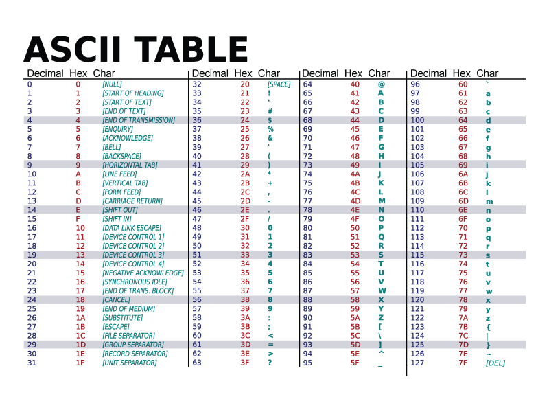
–> The ASCII (American Standard Code for Information Interchange) table is a mapping between human-readable characters and their corresponding binary values. Each character (letter, digit, punctuation mark, etc.) is assigned a specific numeric code. In the context of UART communication, ASCII codes are often used to encode characters for transmission.
–> For example, when transmitting the letter ‘A’ over UART, the following values are relevant:
- ASCII Code: The ASCII code for the letter ‘A’ is 65 in decimal, 0x41 in hexadecimal, and 1000001 in binary.
- Transmission Process: The binary equivalent (1000001) is sent through the UART as a sequence of data bits.

Understanding Number System Conversion
–> Microcontrollers frequently need to convert between different number systems. For example, when a microcontroller wants to send a variable (such as a temperature value) over UART, it might need to convert that variable from an integer to its binary or hexadecimal form.
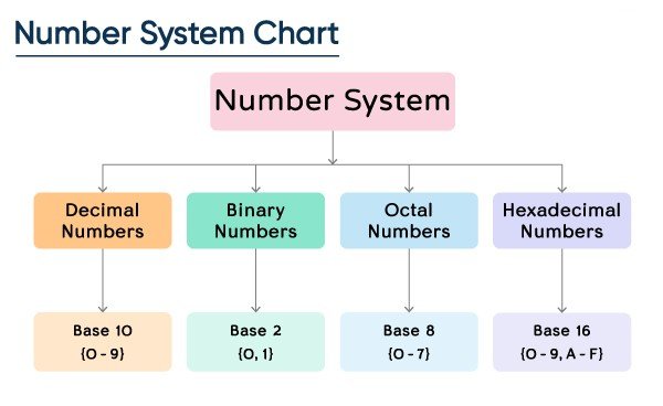
–> Here are some common number systems used in UART communication:
- Binary: The fundamental number system for digital communication. All data in UART communication is ultimately represented as binary (0s and 1s).
- Hexadecimal: Often used for a more human-readable form of binary data, since it’s more compact and easier to understand.
- Decimal: Typically used in programming and general computing, especially when working with user-friendly interfaces.
- ASCII: As mentioned earlier, this character-based encoding represents letters, numbers, and other symbols.

Transmission of a Single Letter (‘A’) via UART
–> Let’s break down how the transmission of a single character, such as the letter ‘A’, works over UART.
Step 1: ASCII Representation of ‘A’
–> The letter ‘A’ has the following representations:
- Decimal: 65
- Hexadecimal: 0x41
- Binary: 1000001
–> These values are derived from the ASCII table, and they represent the character in a way that can be understood by the microcontroller.
Step 2: UART Data Frame
–> UART communication works by packaging the data into a frame. The frame is composed of several elements:
- Start Bit: A single bit (0) indicating the beginning of the data transmission.
- Data Bits: This is where the actual data is stored. For an 8-bit data word, there will be 8 bits, each representing a part of the byte being transmitted. In this case, for the character ‘A’, the data bits will be 1000001 (binary representation of 65 in decimal).
- Parity Bit: This optional bit is used for error checking. If enabled, it helps ensure that the number of 1s in the data bits is even (even parity) or odd (odd parity).
- Stop Bit(s): One or more bits (usually 1) that signify the end of the data transmission. This ensures that the receiver knows when the transmission is complete.
–> The UART frame for transmitting the letter ‘A’ (0x41) would look like this (assuming 1 start bit, no parity, and 1 stop bit):

Step 3: Transmission Process
- The microcontroller will send the start bit (0) to begin the transmission.
- Then, it will transmit the data bits. In this case, the binary representation of ‘A’ (1000001) is sent.
- Finally, the stop bit(s) will be transmitted to mark the end of the communication.
- If the receiver is ready and configured correctly, it will read the data from the UART frame, which it can then convert back into an ASCII character (in this case, ‘A’) or perform other operations depending on the application.
Step 4: Visualization with a Logic Analyzer
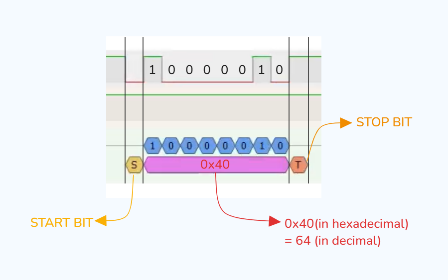
–> A logic analyzer can be used to inspect the transmission of the data visually. If you use a logic analyzer to monitor the UART transmission, you will see the following:
- The start bit (0) marks the beginning of the transmission.
- The data bits (1000001) are transmitted one after the other.
- The stop bit (1) signifies the end of the transmission.
–> The logic analyzer will show these signals as square waves, with the high and low voltage levels corresponding to the binary values (1s and 0s). By looking at the captured signal, you can verify that the data being sent matches what you expect.
UART APIs for Number System Conversions
Below are some basic UART APIs for common number system conversions (inspired by STM32 drivers):
A. Hex to Binary:
B. Character to Binary:
C. Binary to Decimal:
These APIs can be used to convert data formats before transmission or after reception over UART.
UART Ring Buffer Concept

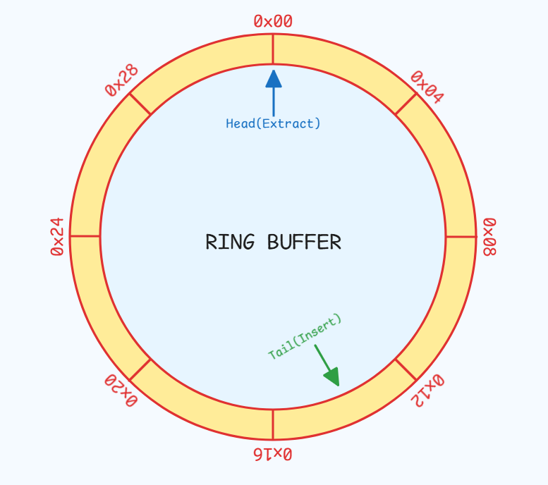
–> A ring buffer (circular buffer) is often used to handle UART data reception. This buffer allows continuous data reception without loss, even when the CPU cannot immediately process it.
How it Works:
- The ring buffer has a fixed size and uses two pointers:
- Head Pointer: Marks the position to write new data.
- Tail Pointer: Marks the position to read processed data.
- When new data arrives via UART, it’s stored at the head position and the pointer advances.
- The CPU reads data from the tail position when it’s ready, and the pointer advances.
- The ring buffer has a fixed size and uses two pointers:
–> This mechanism avoids buffer overflow and ensures smooth data handling in high-speed communication.