Over 10 years we help companies reach their financial and branding goals. Engitech is a values-driven technology agency dedicated.

Gallery

Contacts

411 University St, Seattle, USA

engitech@oceanthemes.net

+1 -800-456-478-23

S32K144 Peripherals

I2C Peripheral in S32K144

So hello guys, welcome back to NXP Semiconductors S32K144 MCU Tutorial series. In the last 2 blogs we had started with S32K144 MCU GPIO Peripheral & UART Peripheral .

In this blog we are going to explore the I2C Peripheral. Going to Start with I2C peripheral. Objective would be to get.

  • familiarity with I2C peripheral for S32K144 MCU.
  • Would be understanding I2C peripheral from Hardware point of view in S32K144 MCU.
  • Going to understand then how to use I2C peripheral via S32K SDK/i2c driver.
  • Would also be demonstrating the i2c_echo_pall sketch.

So read along the blog and do tell me its reviews!

Table of Contents

I2C Peripheral Theory

I2C Peripheral is a serial communication protocol which are used to interface external sensor and display screens to the Host MCU. Sensors like IMU sensor, Torque sensor, OLED Display screen and etc

To know about I2C peripheral theory, you can refer to this blog.

I2C Peripheral in S32K144 MCU

In S32K144 MCU, I2C protocol can be used via 2 peripherals: LPI2C & FlexIO.

I2C protocol in S32K144

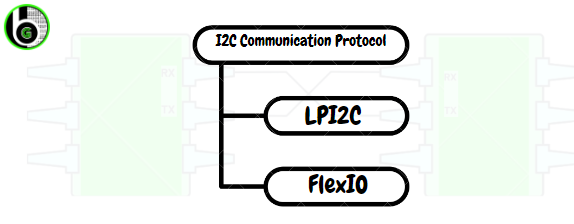
LPI2C is referred as Low Power Inter Integrated Circuit. LPI2C is on chip peripheral only to do I2C communication protocol. I2C is a serial protocol which is done via I2C supported peripherals in the Microocntrollers.

Also, in S32K144 there is FlexIO peripheral through which on-board serial communication protocols like UART, I2C & SPI can be emulated. So through FlexIO peripheral, also I2C peripheral can be implemented. To know about FlexIO peripheral in S32K144, refer to this blog.

Features of I2C via LPI2C peripheral in S32K144 MCU:

  1. LPI2C supports standard-mode, fast -mode , fast-mode plus and ultra -fast modes of operation
  2. High Speed Mode(HS) in slave mode.
  3. Multi-master support, including synchronization and arbitration. Multi-master means any number of master nodes can be present.
  4. Clock stretching support.
  5. Slave addressing via 7 bit( upto 2^7 slaves can be connected at same I2C lines) and 10 bit(upto 2^10 slaves can be connected at same I2C lines).
  6. Support of DMA and Interrupts for both I2C master & slave.
  7. LPI2C also has Support of System Managment Bus Specification, version 2(SMBus), it is used for design of Smart Battery System.

Features of LPI2C master:

  1. Transmit and Receive FIFO of 4 words.
  2. Transmit FIFO can initiate START and STOP conditions for starting I2C communication. As I2C master always initiate the communication session.
  3. Flag and interrupts signal to Start Signals, STOP signals, loss of arbitration, unexpected NACK and command word errors.

Features of LP12C Slave:

  1. There are registers for configuring address if MCU is used as I2C slave. This is done so as to minimize software overhead because of master/slave switching.
  2. Software-controllable ACK or NACK.
  3. Flag and interrupt signals for end of a packet, STOP condition or bit error detection.

How to get started with I2C peripheral in S32K144 MCU

I2C Hardware Pinout in S32K144 MCU

LPI2C Pinout and Hardware Instances

LPI2C peripheral in S32K144 has 1 instance: LPI2I2C0

LPI2C instances in S32K144 MCU

In S32K MCU, LPI2C peripheral can be used in 4 wire schemes & 2 Wire Scheme. For this blog we are going to focus on 2-wire scheme. To know about 4-wire scheme, refer to this blog.

All The LPI2C Instances has 5pins, instead of traditional 2 pins:

  • SCL (Serial Clock): It is used as SCL pin in 2-wire scheme. 
  • SDA (Serial Data):  It is used as SDA pin in 2-wire scheme.
  • HREQ (Host Request): If host request is asserted and the I2C bus is idle, then it will initiate an LPI2C master transfer.
  • SCLS (Secondary I2C clock line): Not used in 2 wire scheme.
  • SDAS (Secondary I2C data line): Not used in 2-wire scheme.
    S32K144 I2C Pins

Each LPI2C instance in S32K144 supports all the 2 pins, with below mentioned pin details. Refer to this blog to know about Pins Signal description in S32K144 MCU

How to do LPI2C Pin Configuration

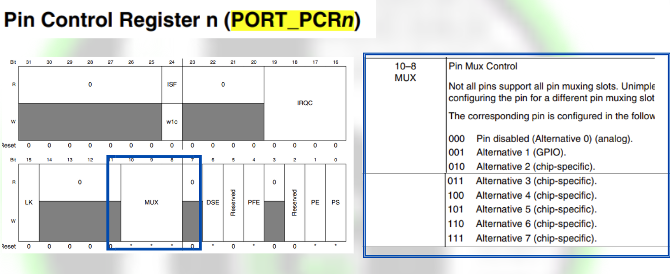
In a MCU a single pin can work as multiple function, so we have to configure that which function we need, accordingly pins have to be configured. This configuration of Alternate functions of pins in S32K144 MCU is done by Signal Multiplexing peripheral. One can configure which pin to use for LPI2C, via Signal Multiplexing peripheral, in which there is a register Pin Control Register (PCR) which has Pin Mux Control bits(MUX) for configuring the alternate functions of the pins.

PCR register of S32K144.

For example, we are using LPI2C0. Now in LPI2C0 for using SCL-SDA pins one can configure PTA3-PTA2 pins:

  • You can see SSS column in the excel in that for PTA3 under LPI2C0_SCL has value of 0000_0011. Last 3 bits of this value represents the MUX values to be configured for configuring PTA3 pin as LPI2C0_SCL pin, in PORT_PCRn register.
  • You can see SSS column in the excel in that for PTA2 under LPI2C0_SDA has value of 0000_0011. Last 3 bits of this value represents the MUX values to be configured for configuring PTA3 pin as LPI2C0_SDA pin, in PORT_PCRn register.

This part of LPUART pins configuration is done internally by S32 SDK/pin driver (Its detail overview is in GPIO Peripheral in S32K144 MCU). When writing the code, we just need to configure the structure  g_pin_InitConfig in which. mux member for the corresponding MCU pin will be assigned value according to last 3 bits of SSS column, as shown below and pass that structure in PINS_DRV_Init().

				
					 /*! @brief Definitions/Declarations for BOARD_InitPins Functional Group */
/*! @brief User number of configured pins */
#define NUM_OF_CONFIGURED_PINS0 2
/*! @brief User configuration structure */
 
pin_settings_config_t g_pin_mux_InitConfigArr0[NUM_OF_CONFIGURED_PINS0] = {
    {
        .base            = PORTA,
        .pinPortIdx      = 2U,
        .pullConfig      = PORT_INTERNAL_PULL_UP_ENABLED,
        .driveSelect     = PORT_LOW_DRIVE_STRENGTH,
        .passiveFilter   = false,
        .mux             = PORT_MUX_ALT3,
        .pinLock         = false,
        .intConfig       = PORT_DMA_INT_DISABLED,
        .clearIntFlag    = false,
        .gpioBase        = NULL,
        .digitalFilter   = false,
    },
    {
        .base            = PORTA,
        .pinPortIdx      = 3U,
        .pullConfig      = PORT_INTERNAL_PULL_UP_ENABLED,
        .driveSelect     = PORT_LOW_DRIVE_STRENGTH,
        .passiveFilter   = false,
        .mux             = PORT_MUX_ALT3,
        .pinLock         = false,
        .intConfig       = PORT_DMA_INT_DISABLED,
        .clearIntFlag    = false,
        .gpioBase        = NULL,
        .digitalFilter   = false,
    },
    
     PINS_DRV_Init(NUM_OF_CONFIGURED_PINS0, g_pin_mux_InitConfigArr0);


At line 13 and 26 you see .mux is assigned with PORT_MUX_ALT_3. The value of this is taken from port_mux_t Enum which is defined in pins_driver.h file as follows. The members defined in this Enum is according to the MUX bits values defined in PCRn register. So according to the value of the last 3 bits of SSS column, we will configure the. mux member of  g_pin_InitConfig structure.

				
					/*!
 * @brief Configures the Pin mux selection
 * Implements : port_mux_t_Class
 */
typedef enum
{
    PORT_PIN_DISABLED            = 0U,  /*0b000!< corresponding pin is disabled, but is used as an analog pin       */
    PORT_MUX_AS_GPIO             = 1U,  /*0b001!< corresponding pin is configured as GPIO                           */
    PORT_MUX_ALT2                = 2U,  /*0b010!< chip-specific                                                     */
    PORT_MUX_ALT3                = 3U,  /*0b011!< chip-specific                                                     */
    PORT_MUX_ALT4                = 4U,  /*0b100!< chip-specific                                                     */
    PORT_MUX_ALT5                = 5U,  /*0b101!< chip-specific                                                     */
    PORT_MUX_ALT6                = 6U,  /*0b110!< chip-specific                                                     */
    PORT_MUX_ALT7                = 7U,  /*0b111!< chip-specific                                                     */
#if FEATURE_PINS_HAS_ADC_INTERLEAVE_EN
    PORT_MUX_ADC_INTERLEAVE      = 8U   /*!< when selected, ADC Interleaved channel is connected to current pin
                                         *   and disconnected to opposed pin
                                         * ADC1_SE14-PTB15 | ADC1_SE15-PTB16 | ADC0_SE8-PTC0  | ADC0_SE9-PTC1
                                         * ADC1_SE14-PTB0  | ADC1_SE15-PTB1  | ADC0_SE8-PTB13 | ADC0_SE9-PTB14 */
#endif /* FEATURE_PINS_HAS_ADC_INTERLEAVE_EN */
} port_mux_t;


I2C SDK for S32K144 MCU

LPUART SDK

S32K SDK/drivers provide an easy to use and quick way to use the LPI2C peripheral in S32K144, which is known as LPI2C SDK.

LPI2C SDK for S32K144 MCU

Each S32 SDK driver can be configured and enabled to use in the project via S32 Configuration Tool. Will be digging into that part, in next section. For now, let’s understand the LPI2C SDK in some detail, so as to use I2C peripheral via LPI2C.

LPI2C SDK files

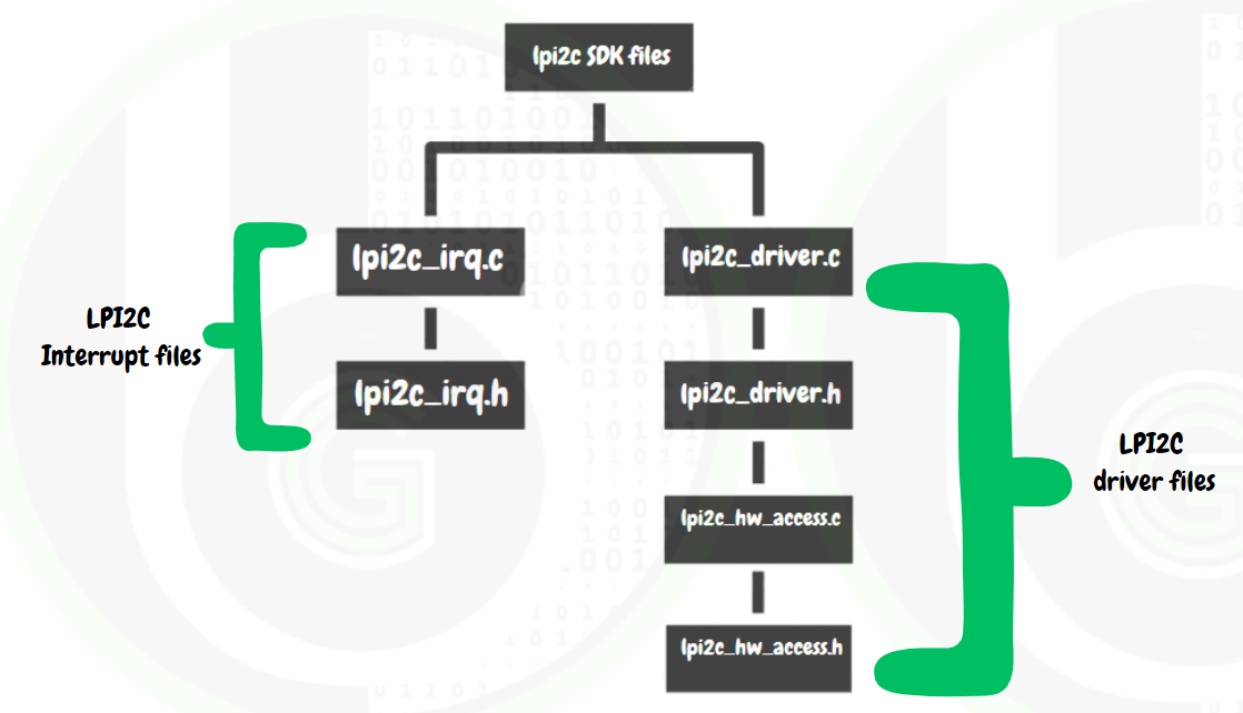
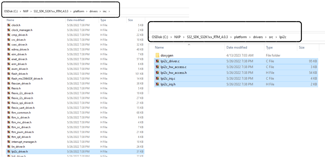
In the SDK of LPI2C there are header and source files for LPI2C Driver and LPI2C Interrupt

  • LPUART interrupt files contains functions for using &configuring of LPUART interrupts and IRQ handler in S32K144 MCU.
  • LPUART driver files contains functions for using/configuration of LPUART Peripheral.
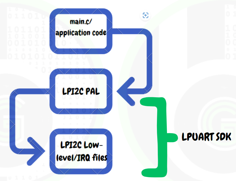
LPI2C Driver

LPI2C driver files are further divided into LPI2C Peripheral Abstraction Layer(PAL) & LPI2C Low Level drivers, as shown below:

LPI2C Driver files
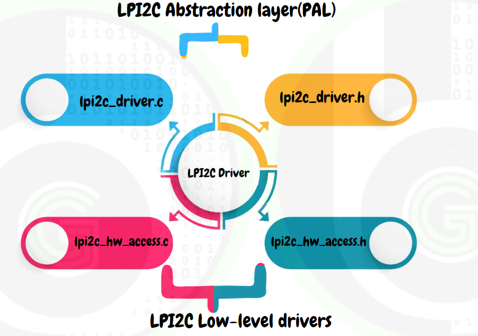
  • LPI2C Peripheral Abstraction Layer(PAL): contains functions and variables that are directly used in main.c or application code. And internally these functions use the LPI2C Low-level drivers & LPI2C IRQ. So if hardware is changed LPI2C PAL would remain same and only internal low-level driver files need to be changed or modified. By this way we don’t have make many changes on application level.
  • LPI2C Low-level driver: contains functions that configures the LPI2C peripheral registers for initializing the peripheral, using the peripheral and processing the data of peripheral at hardware level. These files are the ones which actually interacts with the hardware and make it configurable to our needs. 

In the blogs we will be exploring the LPI2C Peripheral Abstraction Layer files (PAL) in more details, as that would be directly used in our application project development(main.c) and driver creation of I2C modules (Display Screens, Gyroscope sensor and etc)

LPI2C PAL

In LPI2C PAL there are 2 files lpi2c_driver.c and lpi2c_driver.h files.

Let’s get into these files:

  1. lpi2c_driver.h: contains the Enum’s, structures and function declarations that would be used in application code. Only functions which are declared in this header file can be used in main.c or application project.
  2. lpi2c_driver.c: contains the function definitions of the declared functions (uses the low-level driver functions) along with some static functions also that are restricted to use in this file only.

Functions

LPI2C Master Functions
  • LPI2C_DRV_MasterInit: This function is first function to be used in main.c or application code to initialize the I2C peripheral in Master Mode.
				
					status_t LPI2C_DRV_MasterInit(uint32_t instance,
                                    const lpi2c_master_user_config_t * userConfigPtr,
                                    lpi2c_master_state_t * master)


This function has 3 function parameters as follows:

  1. instance: integer number indicating which instance of LPUART we are going to use.
  2. userConfigPtr: Structure pointer have to be sent for lpii2c_master_user_config_t structure
  3. master: Structure pointer have to be sent for lpi2c_master_state_t structure.
				
					/* LPI2C instance */
#define INST_LPI2C0  0U

/* Master module configurations */
 lpi2c_master_user_config_t lpi2c0_MasterConfig0;

/* Initialize LPI2C Master configuration
     *  - Slave address 0x32
     *  - Fast operating mode, 400 KHz SCL frequency
     *  -   See LPI2C components for configuration details
     */
    
lpi2c_master_user_config_t lpi2c0_MasterConfig0 = {
  .slaveAddress = 50U,
  .is10bitAddr = false,
  .operatingMode = LPI2C_FAST_MODE,
  .baudRate = 400000UL,
  .transferType = LPI2C_USING_INTERRUPTS,
  .dmaChannel = 0U,
  .masterCallback = NULL,
  .callbackParam = NULL
};

LPI2C_DRV_MasterInit(INST_LPI2C0, &lpi2c0_MasterConfig0, &lpi2c1MasterState);


  • LPI2C_DRV_MasterSendData: This function starts the transmission of a block of data to the currently configured slave address via non-blocking method. The transmission of data via this API is handled by the Interrupt Service Routine. That is this function returns immediately and we need to call LPI2C_DRV_MasterGetSendStatus() to check the progress of the transmission.
				
					status_t LPI2C_DRV_MasterSendData(uint32_t instance,
                                            const uint8_t * txBuff,
                                            uint32_t txSize,
                                            bool sendStop);


This function has 4 function parameters:

  1. instance: integer number indicating which instance of LPUART we are going to use.
  2. txBuff: buffer pointer, pointing to the data which needs to be send out.
  3. txSize: size of data that has to be sent.
  4. sendStop: specifies whether to generate the stop condition after the transmission.


					     uint8_t masterTxBuffer[BUFF_SIZE];
    /* Definition of the data transfer size */
#define BUFF_SIZE (64u)
     /* Initialize the data buffer */
    for(cnt = 0; cnt < BUFF_SIZE; cnt++)
    {
        masterTxBuffer[cnt] = (uint8_t)cnt;
    }
  
  /* Send a packet of data to the bus slave */
    LPI2C_DRV_MasterSendData(INST_LPI2C0, masterTxBuffer, BUFF_SIZE, true);


  • LPI2C_DRV_MasterSendDataBlocking: This function
				
					status_t LPI2C_DRV_MasterSendDataBlocking(uint32_t instance,
                                    const uint8_t * txBuff,
                                    uint32_t txSize,
                                    bool sendStop,
                                    uint32_t timeout)


This function has 5 function parameters:

  1. instance: integer number indicating which instance of LPUART we are going to use.
  2. txBuff: buffer pointer, pointing to the data which needs to be send out.
  3. txSize: size of data that has to be sent.
  4. sendStop: specifies whether to generate the stop condition after the transmission
  5. timeout:timeout values in miliseconds
				
					     uint8_t masterTxBuffer[BUFF_SIZE];
    /* Definition of the data transfer size */
#define BUFF_SIZE (64u)
     /* Initialize the data buffer */
    for(cnt = 0; cnt < BUFF_SIZE; cnt++)
    {
        masterTxBuffer[cnt] = (uint8_t)cnt;
    }
  
  /* Send a packet of data to the bus slave */
    LPI2C_DRV_MasterSendDataBlocking(INST_LPI2C0, masterTxBuffer, BUFF_SIZE, true, OSIF_WAIT_FOREVER);


  • LPI2C_DRV_MasterReceiveData:
				
					status_t LPI2C_DRV_MasterReceiveData(uint32_t  instance,
                                       uint8_t * rxBuff,
                                       uint32_t rxSize,
                                       bool sendStop)


This function has 4 function parameters:

  1. instance: integer number indicating which instance of LPUART we are going to use.
  2. rxBuff: buffer pointer, pointing to the buffer where to store received data.
  3. txSize: size of data that has to be sent.
  4. sendStop: specifies whether to generate the stop condition after the transmission
				
					     uint8_t masterRxBuffer[BUFF_SIZE];
    /* Definition of the data transfer size */
#define BUFF_SIZE (64u)
     /* Initialize the data buffer */
    for(cnt = 0; cnt < BUFF_SIZE; cnt++)
    {
        masterRxBuffer[cnt] = 0;
    }
  
/* Request data from the bus slave */
LPI2C_DRV_MasterReceiveData(INST_LPI2C0, masterRxBuffer, BUFF_SIZE, true);


  • LPI2C_DRV_MasterReceiveDataBlocking:
				
					status_t LPI2C_DRV_MasterReceiveDataBlocking(uint32_t instance,
                                           uint8_t * rxBuff,
                                           uint32_t rxSize,
                                           bool sendStop,
                                           uint32_t timeout)


This function has 5 function parameters:

  1. instance: integer number indicating which instance of LPUART we are going to use.
  2. rxBuff: buffer pointer, pointing to the buffer where to store received data.
  3. txSize: size of data that has to be sent.
  4. sendStop: specifies whether to generate the stop condition after the transmission
  5. timeout:timeout values in miliseconds
				
					     uint8_t masterRxBuffer[BUFF_SIZE];
    /* Definition of the data transfer size */
#define BUFF_SIZE (64u)
     /* Initialize the data buffer */
    for(cnt = 0; cnt < BUFF_SIZE; cnt++)
    {
        masterRxBuffer[cnt] = 0;
    }
  
/* Request data from the bus slave */
    LPI2C_DRV_MasterReceiveDataBlocking(INST_LPI2C0, masterRxBuffer, BUFF_SIZE, true, OSIF_WAIT_FOREVER);


  • LPI2C_DRV_MasterIRQHandler:
LPI2C Master Data Types

Their are 2 structures that are important and will be used:

  • lpi2c_master_user_config_t:  This structure has members to configure the LPI2C according to user defined settings.
				
					 /*!
 * @brief Master configuration structure
 *
 * This structure is used to provide configuration parameters for the LPI2C master at initialization time.
 * Implements : lpi2c_master_user_config_t_Class
 */
typedef struct
{
    uint16_t slaveAddress;                      /*!< Slave address, 7-bit or 10-bit */
    bool is10bitAddr;                           /*!< Selects 7-bit or 10-bit slave address */
    lpi2c_mode_t operatingMode;                 /*!< I2C Operating mode */
    uint32_t baudRate;                          /*!< The baud rate in hertz to use with current slave device */
#if(LPI2C_HAS_HIGH_SPEED_MODE)
    uint32_t baudRateHS;                        /*!< Baud rate for High-speed mode. Unused in other operating modes */
    uint8_t masterCode;                         /*!< Master code for High-speed mode. Valid range: 0-7. Unused in other operating modes */
#endif
    lpi2c_transfer_type_t transferType;         /*!< Type of LPI2C transfer */
    uint8_t dmaChannel;                         /*!< Channel number for DMA channel. If DMA mode isn't used this field will be ignored. */
    i2c_master_callback_t masterCallback;     /*!< Master callback function. Note that this function will be
                                                     called from the interrupt service routine at the end of a transfer,
                                                     so its execution time should be as small as possible. It can be
                                                     NULL if you want to check manually the status of the transfer. */
    void *callbackParam;                        /*!< Parameter for the master callback function */
} lpi2c_master_user_config_t;


					lpi2c_master_user_config_t lpi2c0_MasterConfig0 = {
  .slaveAddress = 50U,
  .is10bitAddr = false,
  .operatingMode = LPI2C_FAST_MODE,
  .baudRate = 400000UL,
  .transferType = LPI2C_USING_INTERRUPTS,
  .dmaChannel = 0U,
  .masterCallback = NULL,
  .callbackParam = NULL
};


  • lpi2c_master_state_t: This structure has data members, which keep track of the on-going transfers . 
				
					/*!
 * @brief Master internal context structure
 *
 * This structure is used by the master-mode driver for its internal logic. It must
 * be provided by the application through the LPI2C_DRV_MasterInit() function, then
 * it cannot be freed until the driver is de-initialized using LPI2C_DRV_MasterDeinit().
 * The application should make no assumptions about the content of this structure.
 */
typedef struct
{
/*! @cond DRIVER_INTERNAL_USE_ONLY */
    lpi2c_master_cmd_queue_t cmdQueue;      /* Software queue for commands, when LPI2C FIFO is not big enough */
    uint8_t * rxBuff;                       /* Pointer to receive data buffer */
    uint32_t rxSize;                        /* Size of receive data buffer */
    const uint8_t * txBuff;                 /* Pointer to transmit data buffer */
    uint32_t txSize;                        /* Size of transmit data buffer */
    volatile status_t status;               /* Status of last driver operation */
    lpi2c_mode_t operatingMode;             /* I2C Operating mode */
    uint16_t slaveAddress;                  /* Slave address */
    volatile bool i2cIdle;                  /* Idle/busy state of the driver */
#if(LPI2C_HAS_HIGH_SPEED_MODE)
    uint8_t masterCode;                     /* Master code for High-speed mode */
    bool highSpeedInProgress;               /* High-speed communication is in progress */
    uint32_t baudRateHS;                    /*!< Baud rate for High-speed mode. Unused in other operating modes */
#endif
    bool sendStop;                          /* Specifies if STOP condition must be generated after current transfer */
    bool is10bitAddr;                       /* Selects 7-bit or 10-bit slave address */
    semaphore_t idleSemaphore;              /* Semaphore used by blocking functions */
    bool blocking;                          /* Specifies if the current transfer is blocking */
    lpi2c_transfer_type_t transferType;     /* Type of LPI2C transfer */
    uint8_t dmaChannel;                     /* Channel number for DMA rx channel */
    i2c_master_callback_t masterCallback; /* Master callback function */
    void *callbackParam;                    /* Parameter for the master callback function */
    bool abortedTransfer;                   /* Specifies if master has aborted transfer */
    uint32_t baudrate;                      /* Baud rate in Hz*/
/*! @endcond */
} lpi2c_master_state_t;


					 lpi2c_master_state_t lpi2c1MasterState;


LPI2C Slave Functions
  • LPI2C_DRV_SlaveInit: This function is first function to be used in main.c or application code to initialize the I2C peripheral in Slave Mode
				
					status_t LPI2C_DRV_SlaveInit(uint32_t instance,
                                   const lpi2c_slave_user_config_t * userConfigPtr,
                                   lpi2c_slave_state_t * slave)


This function has 3 function parameters as follows:

  1. instance: integer number indicating which instance of LPUART we are going to use.
  2. userConfigPtr: Structure pointer have to be sent for lpii2c_slave_user_config_t structure
  3. master: Structure pointer have to be sent for lpi2c_slave_state_t structure.
				
					  /* LPI2C instance */
#define INST_LPI2C0  0U
  
  /* Slave module configurations */
lpi2c_slave_user_config_t lpi2c0_SlaveConfig0;
lpi2c_slave_state_t lpi2c0SlaveState;
lpi2c_slave_user_config_t lpi2c0_SlaveConfig0 = {
  .slaveAddress = 50U,
  .is10bitAddr = false,
  .operatingMode = LPI2C_FAST_MODE,
  .slaveListening = true,
  .transferType = LPI2C_USING_INTERRUPTS,
  .dmaChannel = 0U,
  .slaveCallback = lpi2c0_SlaveCallback0,
  .callbackParam = NULL
};

  LPI2C_DRV_SlaveInit(INST_LPI2C0, &lpi2c0_SlaveConfig0, &lpi2c0SlaveState);


  • LPI2C_DRV_SlaveSendData:
				
					status_t LPI2C_DRV_SlaveSendData(uint32_t instance,
                                   const uint8_t * txBuff,
                                   uint32_t txSize)


This function has 3 function parameters:

  1. instance: integer number indicating which instance of LPI2C we are going to use.
  2. txBuff: buffer pointer, pointing to the data which needs to be send out.
  3. txSize: size of data that has to be sent.
  • LPI2C_DRV_SlaveSendDataBlocking:
				
					status_t LPI2C_DRV_SlaveSendDataBlocking(uint32_t    instance,
                                           const uint8_t *  txBuff,
                                           uint32_t txSize,
                                           uint32_t timeout)


This function has 3 function parameters:

  1. instance: integer number indicating which instance of LPI2C we are going to use.
  2. txBuff: buffer pointer, pointing to the data which needs to be send out.
  3. txSize: size of data that has to be sent.
  4. timeout:timeout values in miliseconds.
  • LPI2C_DRV_SlaveReceiveData:
				
					status_t LPI2C_DRV_SlaveReceiveData(uint32_t   instance,
                                       uint8_t * rxBuff,
                                       uint32_t  rxSize)


This function has 3 function parameters:

  1. instance: integer number indicating which instance of LPI2C we are going to use.
  2. rxBuff: buffer pointer, pointing to the buffer where to store received data
  3. rxSize: size of data that has to be received.
  • LPI2C_DRV_SlaveReceiveDataBlocking:
				
					status_t LPI2C_DRV_SlaveReceiveDataBlocking(uint32_t instance,
                                               uint8_t  *rxBuff,
                                               uint32_t rxSize,
                                               uint32_t timeout)


This function has 4 function parameters:

  1. instance: integer number indicating which instance of LPI2C we are going to use.
  2. rxBuff: buffer pointer, pointing to the buffer where to store received data
  3. rxSize: size of data that has to be received.
  4. timeout:timeout values in miliseconds.
  • LPI2C_DRV_SlaveIRQHandler:
LPI2C Slave Data Types

Their are 2 structure that are important and will be often used

I2C Demo Code for S32K144 MCU

				
					/*
 * Copyright 2020 NXP
 * All rights reserved.
 *
 * NXP Confidential. This software is owned or controlled by NXP and may only be
 * used strictly in accordance with the applicable license terms. By expressly
 * accepting such terms or by downloading, installing, activating and/or otherwise
 * using the software, you are agreeing that you have read, and that you agree to
 * comply with and are bound by, such license terms. If you do not agree to be
 * bound by the applicable license terms, then you may not retain, install,
 * activate or otherwise use the software. The production use license in
 * Section 2.3 is expressly granted for this software.
 */
/*!
** @file main.c
** @version 01.00
** @brief
**         Main module.
**         This module contains user's application code.
*/
/* MODULE main */


/* Including needed modules to compile this module/procedure */
#if CPU_INIT_CONFIG
  #include "Init_Config.h"
#endif

#include "sdk_project_config.h"


volatile int exit_code = 0;

#include <stdint.h>
#include <stdbool.h>

/* Definition of the data transfer size */
#define BUFF_SIZE (64u)

/* Definition LED */
#define LED_PORT  (PTD)
#define LED_RED   (15u)
#define LED_GREEN (16u)

/* Master TX and RX buffers definition */
uint8_t masterTxBuffer[BUFF_SIZE];
uint8_t masterRxBuffer[BUFF_SIZE];
/* compare buffers definition */
uint8_t compareBuffer[BUFF_SIZE];
bool CheckResult;
/*!
  \brief The main function for the project.
  \details The startup initialization sequence is the following:
 * - __start (startup asm routine)
 * - __init_hardware()
 * - main()
 *   - PE_low_level_init()
 *     - Common_Init()
 *     - Peripherals_Init()
*/
int main(void)
{
    /* Allocate memory for the LPI2C driver state structure */
    lpi2c_master_state_t lpi2c1MasterState;
    /* Variable used for the loop that initializes the data buffer */
    uint8_t cnt = 0;

    /* Initialize the data buffer */
    for(cnt = 0; cnt < BUFF_SIZE; cnt++)
    {
        masterTxBuffer[cnt] = (uint8_t)cnt;
        masterRxBuffer[cnt] = 0U;
        compareBuffer[cnt]  = (uint8_t)(BUFF_SIZE - cnt - 1u);
    }
    /* Initialize and configure clocks
     *  - Configure system clocks and dividers
     *  - Configure LPI2C clock gating
     *  -   see clock manager component for details
     */

     CLOCK_DRV_Init(&clockMan1_InitConfig0);

    /* Initialize pins
     *  - Configure LPI2C pins
     *  -   See PinSettings component for more info
     */
    PINS_DRV_Init(NUM_OF_CONFIGURED_PINS0, g_pin_mux_InitConfigArr0);

    /* Initialize LPI2C Master configuration
     *  - Slave address 0x32
     *  - Fast operating mode, 400 KHz SCL frequency
     *  -   See LPI2C components for configuration details
     */
    LPI2C_DRV_MasterInit(INST_LPI2C0, &lpi2c0_MasterConfig0, &lpi2c1MasterState);

    /* Send a packet of data to the bus slave */
    LPI2C_DRV_MasterSendDataBlocking(INST_LPI2C0, masterTxBuffer, BUFF_SIZE, true, OSIF_WAIT_FOREVER);

    /* Request data from the bus slave */
    LPI2C_DRV_MasterReceiveDataBlocking(INST_LPI2C0, masterRxBuffer, BUFF_SIZE, true, OSIF_WAIT_FOREVER);

    CheckResult = true;
    for (cnt = 0; cnt < BUFF_SIZE; cnt++)
    {
        if (masterRxBuffer[cnt] != compareBuffer[cnt])
        {
            CheckResult = false;
            break;
        }
    }

    /* Turn on Red or Green LED depending on the check result */
    PINS_DRV_WritePin(LED_PORT, LED_GREEN, (1u - CheckResult));
    PINS_DRV_WritePin(LED_PORT, LED_RED, CheckResult);
    /* End of the driver example */

  for(;;) {
    if(exit_code != 0) {
      break;
    }
  }
  return exit_code;
}


Lorem ipsum dolor sit amet, consectetur adipiscing elit. Ut elit tellus, luctus nec ullamcorper mattis, pulvinar dapibus leo.

Author

Kunal

Leave a comment

Stay Updated With Us

Error: Contact form not found.

      Blog