Over 10 years we help companies reach their financial and branding goals. Engitech is a values-driven technology agency dedicated.

Gallery

Contacts

411 University St, Seattle, USA

engitech@oceanthemes.net

+1 -800-456-478-23

Getting Started and Peripheral Coding STM32 MCU's STM32F1

Clock Peripheral in STM32F103

Clock Peripheral Theory

Before getting into how to configure the clock peripheral . We will discuss why microcontrollers need a clock source at all. The processor , the busses and the peripherals that are present in the microcontroller all are reliant on the clock to synchronize their operations. The choice of the clock source depends upon the following factors:-

  1. How much speed is required for a particular application
  2. How accurate the clock source should be i.e the consistency of the period between each clock tick
  3. Power requirements of the application

If there is any significant error in the clock speed it will cause unpredictable consequences for internal microcontroller operations.The operations such as:-

  • The conversion rate of analog to digital signals is governed by a microcontroller clock . The clock determines the rate at which the analog signal will be sampled and how accurate that sampling is done is also governed by the accuracy of the clock.
  • The digital to analog conversion in a microcontroller is also dependent on the clock as the clock speed determines the maximum frequency that can be generated for the analog signal. Also the clock accuracy determines the waveform accuracy 
  • In the case of asynchronous communication the sampling of the incoming data stream is clock dependent as well.Even though in some cases the synchronization of the clock is not necessary but the transmitter and receiver should have the same clock speed for decoding and encoding purposes.

So in a nutshell the clock determines how fast a microprocessor executes the given set of instructions

Clock Peipheral features in STM32F103

The main system clock of the microcontroller is the one from which all the other clocks are derived such as clock to AHB domain, clock to APB domain , clock to the USB, clock to the ethernet etc .  This main system clock is referred to as the SYSCLK. As can be seen in the picture of the clock configuration setting the system clock after being chosen is passed through prescalers  it gets divided into a clock source that goes into HCLK that goes into  AHB bus , DMA , cortex system timer ,FCLK. PCLK1 that goes into  APB1 peripherals and timer clocks .PCLK2 that goes into APB2 peripherals and timer clocks and ADC1. Hence it is responsible for operations such as DMA , ADC. These buses are further connected to the pins that are responsible for ADC , GPIO , SPI and other functionality and in case these pins are not being used the clocks to the pin can be disabled to save power

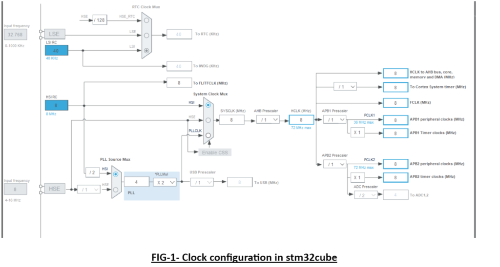
                                                            FIG-1- Clock configuration in stm32cube

To properly drive the SYSCLK there are 3 different sources:-

  1. HIGH SPEED INTERNAL (HSI) oscillator clock(Internal to MCU)
  2. HIGH SPEED EXTERNAL (HSE) oscillator clock(External to MCU)
  3. PHASE LOCKED LOOP(PLL) clock( Internal to MCU) 

There are secondary clock sources as well:-

  1. 40KHz low speed internal RC (LSI)  this used to drive watchdog and optionally RTC(Internal to MCU)
  2. 32.768 KHz low speed external crystal (LSE)  which drives the RTCclock (RTCCLK) the error involved the LSE is less compared to the LSI( External to MCU)

By default the HSI is ON in the microcontroller whereas all the other clocks HSE, PLL etc are OFF. 

Each clock source can be switched ON or OFF independently when not in use to prevent unnecessary power consumption.

HSI

HSI is the default SYSCLK after startup from RESET state, wakeup from STOP OR STAND BY mode or failure of HSE.

It is a low cost clock source having a start-up time less than HSE. The maximum frequency that can be generated is 8MHz using HSI.

It suffers from the demerit that it is less accurate than external crystal oscillator or ceramic resonator

Also as the temperature increases above 25 degree celsius the accuracy decreases

HSE

In case of high speed application HSE can be used as a clock source for SYSCLK . The HSE or the high speed external clock is an external clock that sometimes comes attached to the microcontroller itself or at times requires the usage of an external circuitry.

HSE is faster and more accurate than HSI but suffers from demerits such as slower startup time, high power consumption and times usage of an external circuitry

The maximum frequency that can be generated using HSE clock is 16MHz

HSE  has 3 states ON , OFF and BYPASS

BYPASS is basically  connecting wire to OSC_IN and putting the OSC_OUT in high impedance state i.e bypassing the crystal oscillator as can be seen in FIG-2 external source

                                                      FIG-2 BYPASS mode in HSE

PLL

The PLL or phase locked loop is a clock system that is capable of providing the clock frequency much higher than that of HSI or HSE i.e in case of stm32f1 series it can go up to 72Mhz

Hence for high speed applications PLL is a go to choice . Also peripherals such as USB, Ethernet PHY can not work using HSI or HSE. PLL provides the flexibility of choosing clock frequency without the help of an external oscillator.

SYSTICK clock 

The SYSTICK is required to generate interrupts on a regular basis . It helps the OS in multitasking applications .In applications without an OS is used for timekeeping, time measurement or as an interrupt source. It is derived from the system clock in stm32 and has an usual value of 16MHz. Which means is to generate a delay of 1sec 16000000 has to be loaded on SysTick load value register

Clock peripheral HDK in STM32F103

  • external oscillator pins
  • MCO pins

Clock peripheral SDK in STm32F103

  1. Clock peipheral Files in STM32HAL: 
  2. CLock peripheral low level files and HAL level files
  3. Fucntions descritption and structure decsritption


Clock Peripheral HAL Functions
  • HAL_RCC_OscConfig: 
				
					return type HAL_RCC_OscConfig(RCC_OscInitTypeDef *RCC_OscInitStruct)


Parameter arguments explanation and return type explanantion

  • Argument 1
  • Argument 2
  • argument 3
  • return type
				
					//Demo of how to use functions
				
			
Clock Peripheral HAL Data Types

Data type name( structure name): 

				
					//Code of that structure


					example of how to declare and initailise this structure


How to configure Clock peripheral in STm32F103

//Sysclock = 8MHZ


  •  
  •  
  • Configuring the busses i.e AHB1, AHB2, APB1, APB2 . The AHB bus is faster than APB bus and in case of certain modules they are connected to the same bus .Hence it depends upon the application which bus to use. As can be seen from the picture below the AHB1 takes clock to PORT A , PORT B , PORT C etc . Hence to initialize a pin to a particular port the in RCC AHB1 clock enable register GPIOEN is set to 1 (For Port A GPIOAEN , For Port B GPIOBEN etc)
  • Enabling the clock to that port otherwise the particular pin will not be functional
  •  Creating an instance of the structure and then using the members of the structure set the following:-
  1. PIN – Takes the pin no as input GPIO_PIN_X {where X -0 to 15} 
  2. MODE– Selects the mode the specified pin is supposed to work in . It takes in value Output Push Pull Output Open drain
  3. PULL- It selects the initial value of the pin and takes value no pull up no pull down, pull up or pull down
  4. SPEED- Selects the speed of the working of the specified pin i.e low, medium or high
  5. ALTERNATE- Specifies the alternate function performed by the pin UART TX OR RX , ADC etc

Author

Kunal

Leave a comment

Stay Updated With Us

Error: Contact form not found.

      Blog