What is BootLoader(BL)?
The bootloader is a small chunk of code that gets executed when the MCU powers on or resets. Its main function is to manage the initial startup process, including any necessary checks or updates before the main application code runs.
How BootLoader(BL) is different from Application Software?
Application Software is the function-specific code that you program to perform an MCU-based task(like controlling the motor, displaying information, etc,). But you must be thinking or saying, that your application software also behaves pretty same as bootloader cause everytime you start/reset MCU, it will restart your application code from the beginning, right? But there’s a quite crisp gap between this BootLoader and Application Software which can broaden your understanding of bootloader and application software.
Let’s divide this crisp gap into 3 sub-domains:
- Memory Allocation: If I talk about memory occupied by BL and Application Software. The first thing would be where are these two located and in which memory, answering that, BL is located at the beginning of FLASH memory and it always has some reserved space only which is also write-protected(Thinking why write-protected because to prevent accidental overwriting during normal operation) whereas application software is also stored in FLASH memory only but it’s below the space allocated to BL.
- Execution Flow: Upon power-on or reset, the microcontroller’s program counter starts executing code from the beginning of the flash memory, where the bootloader is located. After the bootloader completes its tasks (like, checking for updates, and validating the application), it will typically jump to the application’s start address (which is known and fixed in the bootloader code) to begin executing the application.
- Update Process: A well-developed bootloader can help you even in handling firmware updates. It can receive new application code, erase the old code, and write the new code to memory. The application cannot typically update itself. It relies on the bootloader to manage this process. The application’s major focus is on running the device’s features and does not deal with the update or integrity checks.
Let's understand with a analogy
Taking an analogy with our expertise field of automotive embedded systems.
- Considering ourselves as an OEM, we have been reported a problem. A software bug is discovered in the ECU that controls the braking system. This bug causes the braking system to occasionally misbehave under specific conditions, such as when the vehicle is driving downhill. Diagnosing this issue requires an early solution because the bug needs to be fixed quickly to ensure the safety of the vehicles on the road. During the update of this bug fixing, the vehicle’s battery drains, and the update process is interrupted:
- With a Bootloader: When power is restored, the bootloader detects that the application firmware is corrupted or incomplete. It can either retry the update automatically or revert to a backup firmware version, ensuring the vehicle remains operational and can be updated again. I agree in this condition driving is not safe, but at least the car can operate so that it can be driven to repair with full caution.
- Without a Bootloader: The ECU might attempt to boot the corrupted application, resulting in a system crash or malfunction. The vehicle may not start or may exhibit erratic behavior, requiring a technician to manually intervene and repair the ECU, which could be time-consuming and costly.
- EDIT: Just found another real-life example. As we all know windows push too much of FOTA(Firmware Over-The-Air), out of which some take too much time to restart and some get applied with restart. Now you must have seen this screen will update.
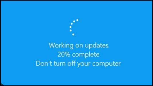
This “DON’T TURN OFF YOUR COMPUTER” message is also displayed for the very same reason, how power disruption can lead to the bricking of your laptop. But you must be curious what exactly what will happen if I cut off the power supply, and power up the device again, right?
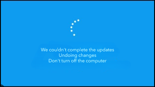
As a bootloader function, this interruption will be acknowledged and the bootloader will roll back to the previous functional update. You might see below mention image on start-up.
IMPORTANT: Avoid trying this at home, this maneuver costs us to retrieve the data but unfortunately all core OS files and applications were corrupted and no longer responded for usage, we tried some troubleshooting using the window troubleshooter, but it wasn’t effective. At last, we installed a completely fresh OS from scratch.
I would expect that you have completely understand the “WHY” and “WHAT” of BootLoader. Now, it’s time to understand the “HOW” of bootloader.
Important Terminology in BootLoader
Memory Management
Memory management is quite an interesting concept that can also help in relating to real-world applications. As we understand the chronology of the working of a bootloader, which is firstly a bootloader will get which now will be followed by application software. Now basically there can be different executions of application software, let’s brief all possible ways:
- Executing Directly from Flash Memory: This specific condition is noticed in most of the embedded MCUs where the bootloader and application software are placed in FLASH memory only. Flash memory is non-volatile, meaning it retains data even when the power is off.
- Copying to RAM Before Execution: In some cases, the application code might be copied from flash memory to RAM before execution. This approach is more common in systems where high performance is required or where the flash memory is slower than RAM. The major reason behind using RAM for execution, RAM is typically faster than flash memory.
- Overlaying: In systems with limited RAM, overlaying is a technique where only a portion of the program is loaded into RAM at any given time, with different parts of the program being loaded and unloaded as needed.
- Virtual Memory Techniques: This specific technique is very common nowadays you must see that recent smartphones have this feature called RAM EXTENSION, where a portion of storage is accumulated to RAM for its R/W access. Parts of the application can be swapped in and out of physical RAM as needed.
Such strategies are important to optimize performance, manage limited memory resources, and ensure the execution of software. These techniques help balance the trade-offs between speed, memory usage, and power consumption.
Boot Manager
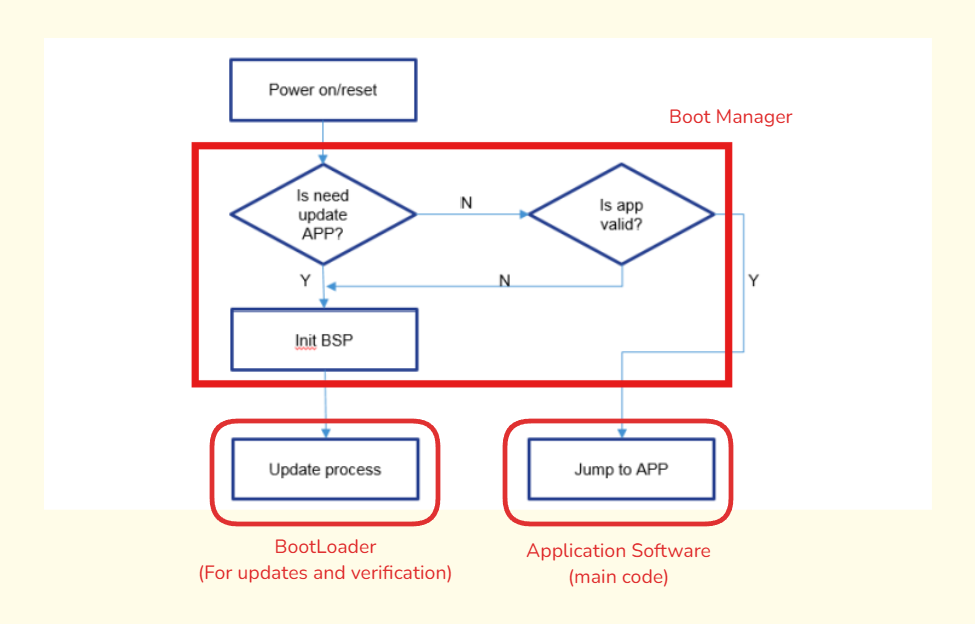
When your device powers on or resets, the boot manager steps in to decide what happens next. It’s like the middleman between the hardware (your microcontroller) and the software (your application and possibly a bootloader).
What Does It Do?
Decision Maker: The boot manager’s main role is to decide what should run. Should it go straight into your main application, or should it handle things over to the bootloader for tasks like updates or recovery?
Prioritization: It checks if there’s something special that needs to be done—like if you’ve flagged the system for an update.
Safety Check: Before anything gets executed, the boot manager ensures everything is in good shape. It verifies if your application software is valid and hasn’t been corrupted. If there’s a problem, it might keep the system in a safe state or initiate a recovery process.
Let’s understand this boot manager with same analogy of Windows:
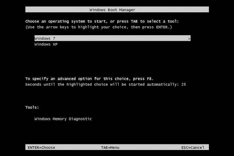
You must have seen the above image in some computer/laptop, where you are asked to choose different options of OS(Operating System) kernel. Some of may have seen this same screen but with options like Windows Manager, Linux System, or Ubuntu.
But nowadays with a recent laptop and computer, you may not notice this boot manager screen cause it chooses the default boot manager as Windows Boot Manager. To see this boot manager, you try F12(common in most OS kernels, if doesn’t work try another function key) when you power up the laptop from the shut-down condition. Holding this function key while powering up the laptop, helps you to enter the state machine condition where boot manager will not choose default boot manager and asks you to choose with option also.
Image Structure ,Verification and Storing
In the context of boot loading, an “image” refers to the complete, packaged version of the code that’s ready to be loaded. It’s a compiled, binary file that contains everything the device needs to run the application software.
Image Structure:
An image typically consists of several components:
Bootloader Code (Optional): This is the code that runs first and may handle tasks like updates or recovery before handing control over to the main application.
Application Code: This is the main part of the image, containing the application program that will run on the device.
Metadata: Includes various pieces of information needed by the bootloader or the device, such as:
- Memory Addresses: Where different parts of the code should be loaded in memory.
- Version Information: To ensure the correct version is running.
- Configuration Data: Settings that the application may need to run correctly.
- Checksums/Hashes: Used to verify the integrity of the image.
Image Verification:
- The Bootloader should have Image verification to prevent untrusted programs from running.
- Verification on new images may happen for just the first time or with each reset cycle, but
this is overhead on the system. - Instead, we can verify the image for the first time and then set the image verification flag.
Image Storing:
- The images can be saved in the free space of internal or external memory.
- Images in external flash should be kept
encrypted. - Images in internal flash should be decrypted.
- The stored image can also be flagged with “ACTIVE”, “INACTIVE”, and “VALIDATED”. These flags help in failure management and recovery purposes.
Interrupt Vector Table
The Interrupt Vector Table (IVT) is a crucial part of a microcontroller architecture, serving as a lookup table that helps the system respond to interrupts. Like, consider this as a table where the microcontroller can see which interrupt means execution of which ISR. You might get confused by the above-given gist, so let’s explain to you in detail:
- Working:
- Interrupts and Vectors: When an interrupt occurs, the MCU needs to know which piece of code to execute to handle that specific event. The interrupt vector is essentially a pointer or address to the specific interrupt handler (a function or routine) that will handle the interrupt. Similarly, when combining multiple interrupt vectors in a single table, it’s called a Vector Interrupt Table.
- Location in Memory: The IVT is typically located at a fixed location in the memory. The exact location can vary depending on the architecture, but it is usually at the beginning of the memory space.
- Handling an Interrupt: When an interrupt occurs, the MCU uses the interrupt number (which identifies the type of interrupt) to look up the corresponding address in the IVT. The MCU then jumps to that address and begins executing the ISR. After the ISR is completed, control is returned to the original program where it left off.
- Working:
Let me show you how a IVT looks like, for better understanding:
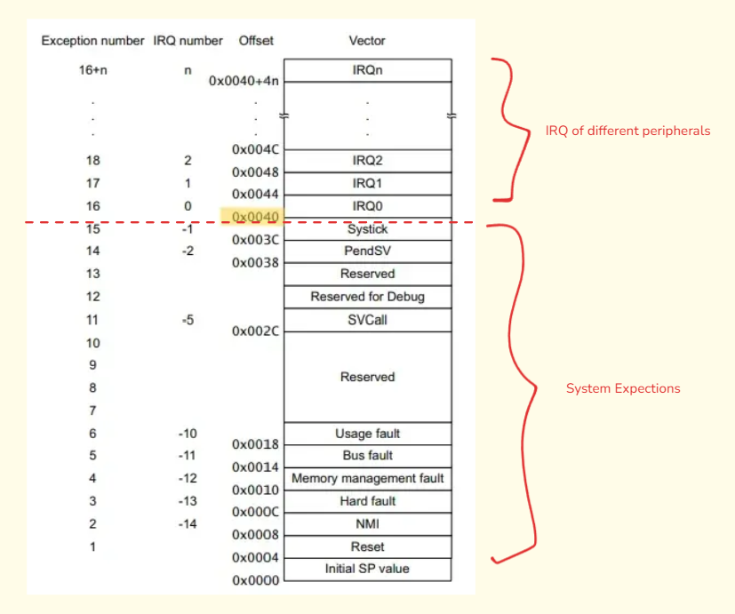
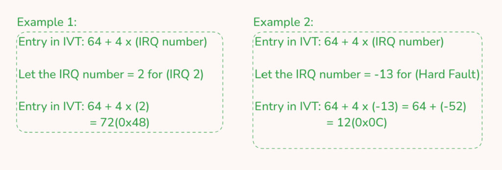
Now, the Exception Number section is defined by ARM MCU for indexing whereas IRQ Number sets the priority of the interrupts(lower number -> higher priority). Vector stores the pointer for the interrupt to be executed and then called.
Now, it’s time to see some calculations of IVT in a gist. Our base offset for calculation will be 64(0x40) because it divides the Peripheral IRQ and System Exceptions.