UART Peripheral in S32K144
Introduction
–> UART Peripheral is one of the most common communication modules present in every series of microcontrollers. For Crisp and Short UART understanding as a concept, redirect yourself to this BLOG, it might take a couple of minutes to have an overlayed understanding. Now, UART is used in GPS modules or other wireless modules like Bluetooth and WiFi. GPS Modules- Use UART to exchange NMEA strings for positioning data. Bluetooth (e.g., HC-05)- Employs UART for wireless data transfer and pairing. Wi-Fi Modules (e.g., ESP8266, ESP32)- Use UART for sending AT commands and receiving responses.
–> In S32K144, we’ll be referring to the UART as LPUART because the UART supported in S32K144 is a low-power UART called LPUART(Low Power Universal Asynchronous Receiver/Transmitter).
–> NOTE: A single instance of UART contains a pair of a TX pin and an RX pin.
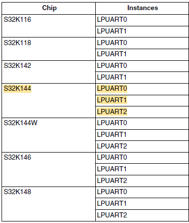
–> Below are mentioned table of LPUART instances supported in different series with highlighted sections of our development board:

Features of UART
1. Communication Basics
- Full-Duplex NRZ Format: The LPUART operates in full-duplex mode, meaning it can send and receive data simultaneously. It uses the standard non-return-to-zero (NRZ) format, where the signal stays constant for a “0” or “1” bit. This ensures efficient and reliable data exchange between devices.
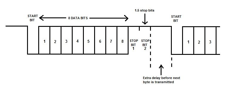
- Configurable Character and Stop Bits: You can define the size of data packets, ranging from 7 to 10 bits, depending on the application. Additionally, the LPUART allows 1 or 2 stop bits, which signal the end of a data frame and ensure proper synchronization between the transmitter and receiver.

2. Baud Rate Flexibility
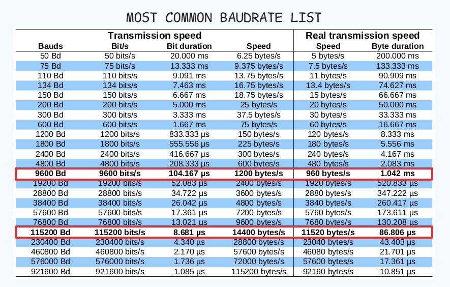
- Programmable Baud Rates with Oversampling: The Baud rate determines the speed of data transfer. LPUART provides flexibility with a 13-bit divider to set precise baud rates and offers oversampling ratios (4x to 32x) to improve accuracy and reduce noise during data transmission.
- Asynchronous Bus Clock Support: The baud rate configuration is independent of the main bus clock, allowing the module to work seamlessly even in low-power Stop modes. This feature makes it highly adaptable to power-efficient designs.

3. Data Handling Methods
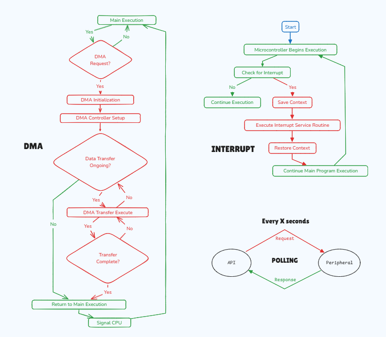
- Interrupt, DMA, or Polling Options:
- Interrupts: The processor is notified when an event occurs, like when the data register is empty or full. This is ideal for real-time operations.
- DMA (Direct Memory Access): Automates data transfer between memory and peripherals without involving the processor, ensuring high-speed communication for larger data sets.
- Polling: The processor repeatedly checks the status of the module, suitable for simpler or less time-critical tasks.
- Interrupt, DMA, or Polling Options:

4. Error Detection and Handling
- Comprehensive Error Detection: The module is equipped to detect and handle common communication issues:
- Parity Errors: Check if data integrity is maintained during transmission.
- Framing Errors: Identify missing stop bits, which can occur due to timing mismatches.
- Noise Errors: Detect unwanted signal fluctuations that could corrupt the data.
- Overrun Errors: Handle situations where the receiver buffer is overwhelmed by incoming data.
- Idle and Break Detection: LPUART can detect idle conditions (no data being sent) and break signals (prolonged low states), which are often used in protocols like LIN for synchronization and error recovery.
- Comprehensive Error Detection: The module is equipped to detect and handle common communication issues:
5. Wake-Up Features
- Three Wake-Up Methods: The module supports multiple ways to wake the processor from low-power modes:
- Idle Line Wake-Up: The processor wakes when the communication line remains idle for a specific duration.
- Address Mark Wake-Up: Only wakes the processor when a particular address is detected in the data stream.
- Receive Data Match Wake-Up: The processor is triggered only if specific data matches predefined patterns, reducing unnecessary processing.
- Three Wake-Up Methods: The module supports multiple ways to wake the processor from low-power modes:

6. Advanced Address Matching
- Automatic Address Matching: To simplify communication with multiple devices, the LPUART can automatically detect specific addresses in the data stream, such as:
- Address Mark Matching: Recognizes a specific address in the data flow.
- Idle Line Matching: Matches an address when the line is idle.
- Start/End Matching: Detects when address transmission begins or ends.
This feature minimizes the need for constant software monitoring, reducing the load on the processor.
- Automatic Address Matching: To simplify communication with multiple devices, the LPUART can automatically detect specific addresses in the data stream, such as:

7. Hardware Optimization
- Parity Generation and Polarity Selection: The module can automatically generate parity bits (for error-checking) during transmission and check them during reception. It also allows you to invert the signal polarity for transmitter and receiver pins to meet specific hardware requirements.
- Independent FIFOs for TX and RX: Separate First-In-First-Out (FIFO) buffers for transmitting and receiving data provide efficient data management. You can also configure thresholds (watermarks) to trigger interrupts or DMA requests when the buffer reaches a certain level.
8. Flow Control and Specialized Formats
- Hardware Flow Control: LPUART supports Request-to-Send (RTS) and Clear-to-Send (CTS) signals, which coordinate data flow between devices. This avoids buffer overflows and ensures smooth communication, especially in high-speed systems.
- IrDA Support: For infrared communication, the module supports the IrDA 1.4 protocol with Return-to-Zero-Inverted (RZI) formatting and adjustable pulse widths, enabling compatibility with infrared-based systems.
9. Power and Idle Management
- Low-Power Compatibility: The module is designed to work efficiently in low-power modes, such as Stop mode. It can detect idle lengths (1 to 128 idle characters), making it suitable for energy-efficient designs.
Author
