
The clock peripherals of S32k1xx have 3 modules that configure the clocks of the S32K1xx MCU’s.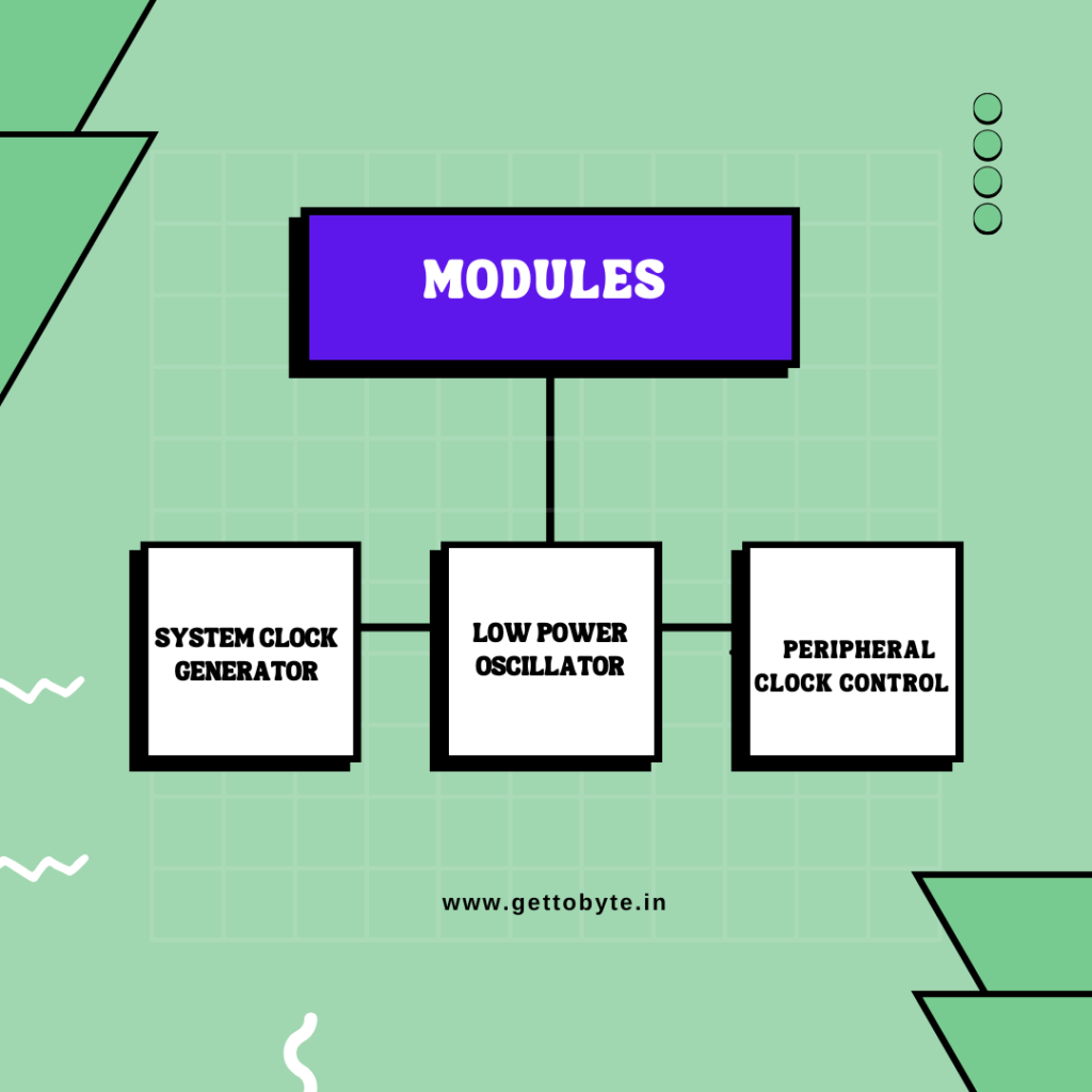
The clock peripherals are basically divided into three modules
- System clock generator
- Low power oscillator
- Peripheral clock control
System clock generator: – This Module generates the Core system clock which is the most important and crucial part. Via this Core system clock, all the peripherals get the clock frequency. So, for generating core system clocks there are 4 sources that can be done. The SCG supports four clock sources, as below: 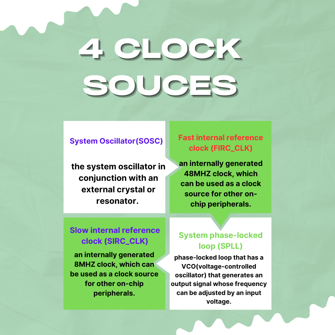
- System Oscillator(SOSC):– the system oscillator in conjunction with an external crystal or resonator. That generates a reference clock for the MCU. The frequency of SOSC lies in between XTAL & EXTAL…
- Fast internal reference clock (FIRC_CLK):- an internally generated 48MHZ clock, which can be used as a clock source for other on-chip peripherals.
- Slow internal reference clock (SIRC_CLK):– an internally generated 8MHZ clock, which can be used as a clock source for other on-chip peripherals.
- System phase-locked loop (SPLL):– phase-locked loop that has a VCO(voltage-controlled oscillator) that generates an output signal whose frequency can be adjusted by an input voltage.
Peripheral clock control (PCC):- This module basically configures, controls, and generates the clock for all the peripherals of the MCU via system clock frequency. To conserve the power most modules’ clocks can be turned off by configuring the CGC field of the peripheral control register in the PCC module. These fields are cleared after any reset, which disables the peripheral clock of the corresponding module.
Note: We will be mainly focusing on the above two clock modules only for our initial development. Understanding and learning.
Low power oscillator (LPO):- an internally generated low power oscillator clock with a typical frequency of 128 kHz which can be used as the clock source for modules operational in low power modes.
Firstly, go to the clock tree view and change the external clock oscillator value (SOSC) from 8mhz to 16mhz.
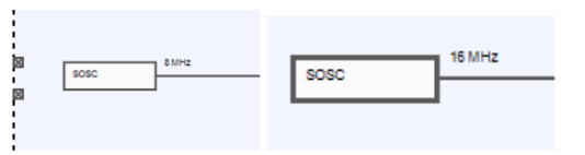
- Mow in Clock Tree View. Initially the SPLL, when SOSC is 8mhz as given in the below fig, that is SPLL_VCO is 224 MHz and After dividing by /2, SPLL_CLK becomes 112 MHz
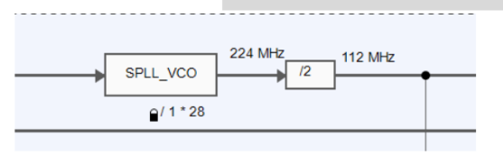
- Now as we have changed the SOCS value to 16 MHz, so these values have become SPLL_VCO is 448 MHz and after the divider value (/2), SPLL_CLK is 224 Mhz.
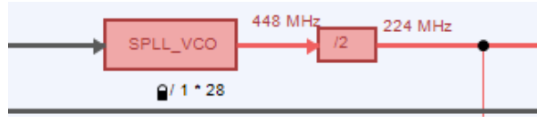
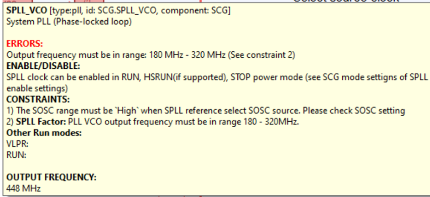
Now as we can see after 16 MHz, it is showing an error, that is the box has become red, hovering on it we can see what the error is. you need to configure the SPLL_ VCO within 180-320 MHz and SPLL_CLK within 90-160 Mhz. And both of these values are getting out of the limit, because of which the red box comes up. So, calculate the value of dividers and multipliers of SPLL in such a way that it is first of all within the allowed limits, shown in the error box. 
- So, we have selected the Multiplier of SPLL_VCO as 3 and the divider of SPLL_VCO as 36, which results in SPLL_VCO as 192 MHz and after the divider value which is fixed for SPLL that is /2, our SPLL_CLK becomes 96 mhz. Now as SPLL_VCO is 192 MHz and SPLL_CLK is 96 MHz, that is within the allowed limits.
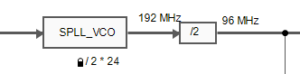
- So our error box is removed now from SPLL.
If the clk is configured properly and you follow the run mode’s clock minimum frequency, then it will not show any error like this.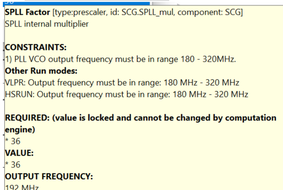
- Now we have to select the clock source for the System Clock Generator (SCG). So that’s what we are going to do now. By double clicking on the SCG module we can see the drop down as shown.
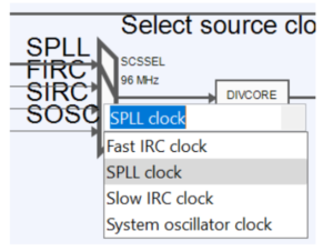
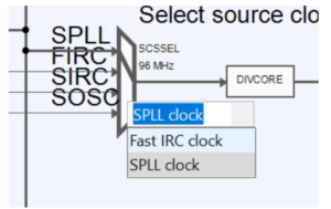
- Now Change the SCG to SPLL_CLK for both modes RUN and HSRUN Mode and the SCG is configured using the SPLL_CLK, which we have done in steps 2 & 3.
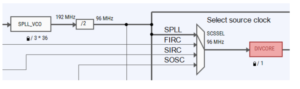
Select Source clock to SPLL in RUN and HSRUN Mode
So now we have configured the System Clock value as 96 Mhz, by configuring the SPLL as mentioned in steps 2&3 and selecting SCG as SPLL_CLK in step 4.
Now, From the SCG, our core and system clock is being inherited. As you can see:
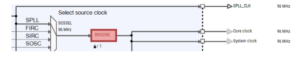
But you can see DIVORCE is red, hovering over it, it says that:
Means we have to reduce the System Clock from 96 Mhz to 80 Mhz so that it comes in Limit of the System clock is 80 Mhz in Run Mode.
So we are dividing System Clock by 6, so that it results in 96/6= 16Mhz. So selecting DIVORCE value as 6 in Run Mode and DIVORCE as 3 in HSRUN Mode.


After updating the code(Step 8 of previous Section), if we navigate to the project explorer and navigate to our hello_world_s32K144 project you will see their is folder created by the name of board. Under this folder only all the .c/.h files from the S32 Design Studio would be generated corresponding to changes we do in peripherals.
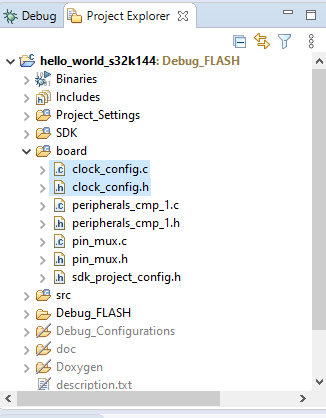
Now under the folder board, one can see all the generated .c/.h files for the corresponding S32K peripheral after doing configuration in S32 Config Tools. We are going to focus on clock peripheral configuration files, in this blog.
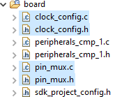
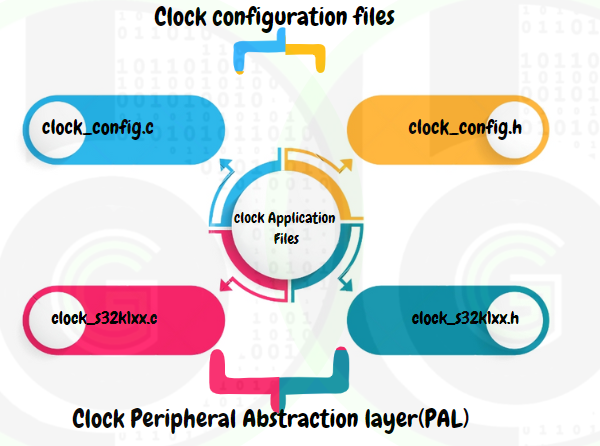
Their are 2 files being generated clock_config.h and clock_config.c after doing clock configurations in S32K144 MCU using S32 Config tools.
Both of these files contains the user input values for the clock peripheral that we have configured in above sectionto use, like: value of presaclers- multipliers, which clock source to use, which clock to be enabled and etc. There is use of structure’s, structure array’s and pointers for storing the user input values and values are represented in the form of enum’s data types, Boolean data types and mathematical numbers.
S32 SDK driver provides an easy to use and quick way to use the Clock Peripheral in S32K144, using its Clock Manager driver Module.
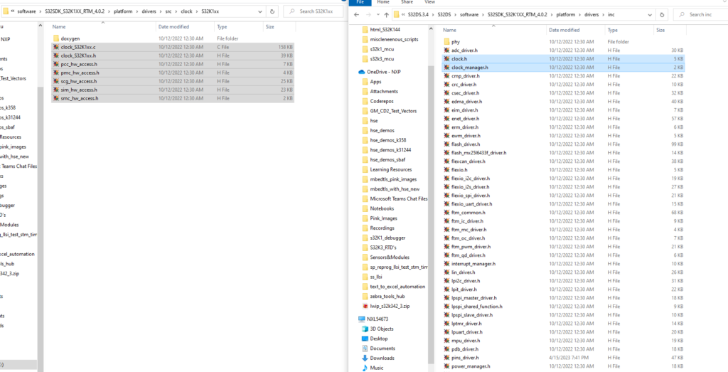
Each S32 SDK driver can be configured and enabled to use in the project via S32 Configuration Tool. Will be digging into that part, in next section. For now, let’s understand the Clock Manager SDK in some detail, so as to use Clock peripheral.
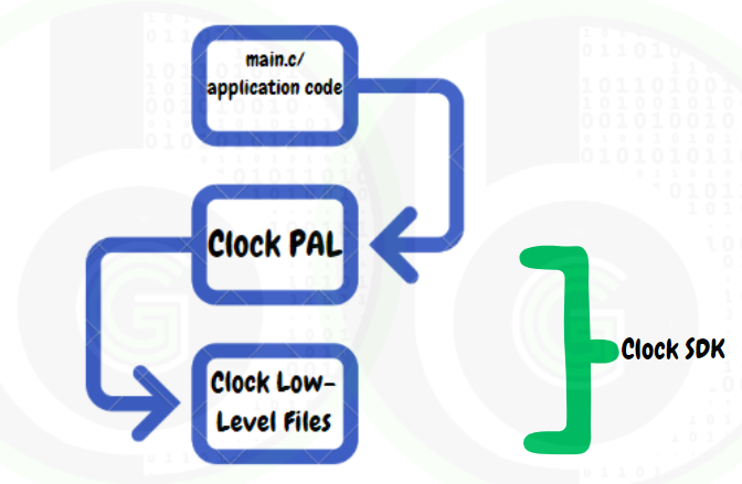
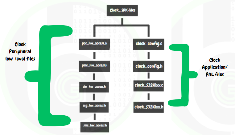 In the SDK of Clock Manager there are header and source files for Clock PAL( Peripheral Abstraction Layer) and Clock Low-Level Files:
- Clock Low-Level Files: contains functions that configures the Clock Peripheral registers for initializing the peripheral, configuring the Peripheral and processing the data of peripheral at hardware level. These are the only ones which actually interacts with the hardware and make it configurable to our needs.
- Clock Application/Peripheral Abstraction Layer(PAL): contains functions and variables that are directly used in main.c or application code. And internally these functions use the Clock Low-level Driver files.
So if hardware is changed out of any S32K1xx family of MCU’s, Clock peripheral would remain same and only internal low-level driver files needs to be changed or modified. By this way, we don’t have to make many changes on application level.
In the blogs we will be exploring the Clock Manager Peripheral Abstraction Layer files (PAL) in more details, as that would be directly used in our application project development(main.c) and doing custom Clock Configuration.
Clock Manager PAL
In CLOCK_CONFIG PAL there are 2 files CLOCK_S32K144.c and CLOCK_S32K144.h files.
Lets get into these files:
CLOCK_S32K144.h: contains the enums, structures and function declarations that would be used in application code. Only functions which are declared in this header file can be used in main.c or application project.
CLOCK_S32K144.c: contains the function definations of the declared functions(uses the low-level driver functions) along with some static functions also that are restricted to use in this file only.
Functions
CLOCK_DRV_Init: This function is the first function that has to be used in CLOCK_S32K144.h to initialize the clock in the MCU.