
Table of Contents
Introduction
Now that we understand the basics of Microcontrollers (MCU), let’s now talk about the peripheral circuitry in detail and get the idea of some of the more important terms of MCU in detail.
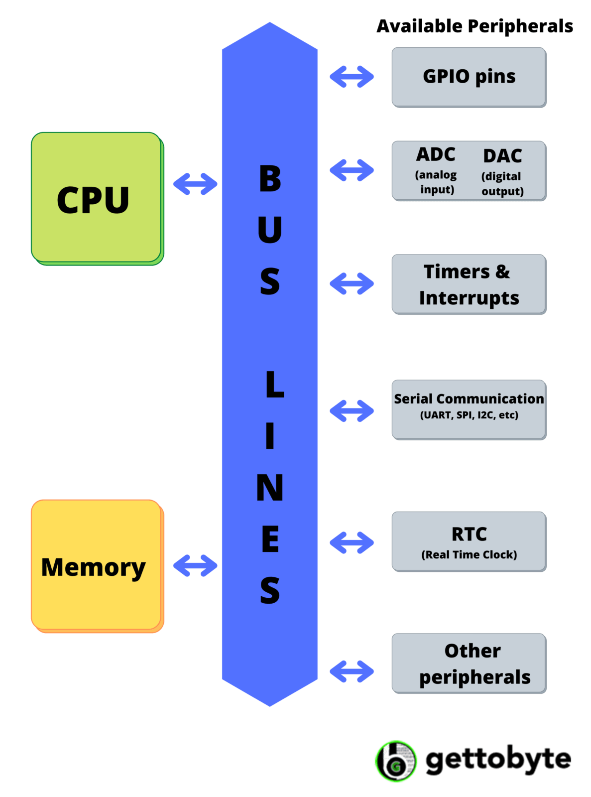
As we know that MCU consists of CPU, memory, and peripherals. Memory is used to store the data and some set of instructions which is fetched, decoded, and executed by the CPU as per the requirement through peripheral i.e., input and output devices to maintain the signal flow.
Some of these input-output ports are shown in Fig.1 and include:
- ADC (Analog to Digital Convertor):
Used for the incoming analog signals which are then converted to digital values in the output form.
- DAC (Digital to Analog Convertor):
Used for the conversion of incoming digital data into analog signals at the output.
- RTC (Real-Time Clock):
Used to empower exact time estimations and time-of-day checking, and is generally used by processes that require or are reliant upon a time.
- UART (Universal Asynchronous Receiver Transmitter):
Used to transmit the parallel data into serial form and vice versa.
GPIO (General Purpose Input Output)
GPIO (General Purpose Input Output)
GPIO is an important peripheral in a MCU as it helps in the transmission of both incoming as well as outgoing signals. As an output, it can be used to send the HIGH(1) or LOW(0) signal at the corresponding configured output pin and as an input, it can be used to detect the outside world digital signal: HIGH(1)/LOW(0).
Now a question may arise why it is called general-purpose? MCU consists of pins(peripherals) for the interaction (i.e., to transmit data or signals) The ports present in the MCU have pins that are meant for either receiving (input) or either sending (output) the data or signals. But GPIO is the flexible pins i.e., these pins can be used to send as well as receive the data or signals ( can be used for input and output both).
GPIO operates that the digital values (0’s and 1’s) when sent to the external device, while programming, will be easily converted to the signals (LOW or HIGH), just like a simple DAC.
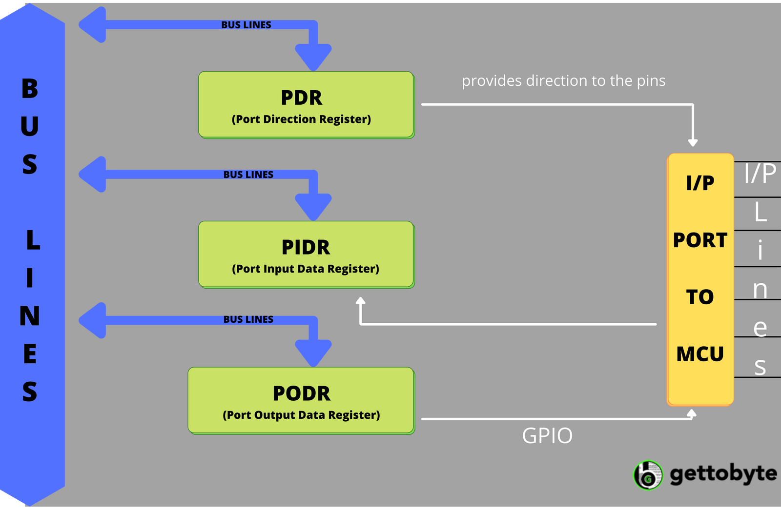
Since we know that registers are present inside the CPU to carry out all the operations, storing the results, execution status, and other relevant information required by the CPU for a hassle-free execution. We will now understand about the general-purpose registers these are some of the GPIO peripheral internal registers which are used.
- Port Direction Register (PDR):
This register sets the direction of each GPIO pin i.e., whether input or output.
- Port Input Data Register (PIDR):
This register updates the status of the incoming signals i.e. if the signal is LOW, it sets the register bits to 0 and if the signal is HIGH it sets the register bits to 1. The signals are read by the CPU in a stack operation. Here an interesting thing to note is that no value is saved instead the CPU after reading, changes the signal state.
- Port Output Data Register (PODR):
This register transmits the message to the outgoing signals i.e., if the data is 1, the LOW signal will be sent and if the data is 1, the HIGH signal will be sent. The signals are written by the CPU in a stack operation and are stored in this register, unlike PIDR, until overflow is encountered.

Timers and WatchDog Timer
As humans, we always keep a track of time. Yes, I am referring to Time Management. How much time I did my studies, how much time I played, how much time I invested in my innovations, and so on. Similarly, when we are working with MCU many applications require timers for their evaluation process or further task. For example, sometimes the user wants to know how much time has been taken to perform a particular set of tasks, at what time what instruction was executed, and so on. Here in MCU, we have a timer as a peripheral function.
Now a question may arise like this timer control can be done by software as well? So what is the need for an extra peripheral function? To answer this, let’s understand this with the help of an example.
Consider that a certain set of instructions takes 0.5µs for its complete execution. That means in 0.5 seconds 500,000 instructions will execute. Hence one major problem will be that the CPU\’s major workforce will indulge in counting thousands and millions, instead of doing some other task. Secondly, there will be no user-customized time increments like 1/50fs (where fs is an input parameter).
Another major issue includes CPU clock speed. If the instructions run at a different clock speed, the wait time will change too. It will be a tedious process if you should make the clock speed the same because then every time you need to change the program code, and may end up with lots of errors.
So keeping all these things in mind, we have a separate peripheral function for the timer. MCU timers are used to count at specific times and to alert the MCU when an interrupt (we will understand this in the interrupt section) is encountered.
Now let’s understand about Watchdog Timer (WDT) also known as COP (computer-operating-properly). This timer distinguishes and reacts to the CPU glitches, so the framework can recover from out-of-control programs that somehow or other can lead to freezing the system. When the program gets started, a predetermined time count gets written in the WDT, which keeps on decreasing as time-lapse. Now here two cases arise.
- If the program terminates without any errors, the counts in the WDT get erased just before the execution completes.
- If an error is encountered, nonetheless, the WDT count will keep decreasing. At the point when the value dips under 0 (an underflow condition), the WDT will interfere with cautioning the CPU that an error has happened.
WDTs are critical in frameworks that should not be allowed to freeze—and, specifically, in frameworks (like embedded systems) where clients can only with significant effort act to reset the actual framework.
Serial and Parallel Communication
Just like we humans interact with the environment through our body parts, MCU also interacts with the devices(like sensors, etc.) through the peripheral by means of communication. This communication could be of two types:
- Parallel Communication:
Communication is established by using GPIO where, let’s say 8 pins are selected to transfer 8 bits of data in a single go, which is termed as a parallel combination. Here data gets transferred through parallel lines in a single take.
- Serial Communication:
When the same 8-bits data is sent bit by bit, it is termed serial communication. Since data is transferred from the single line, hence bit by bit transmission, and hence require less number of pins and wire connection.
Since the communication process has both serial and parallel communication MCU, therefore, must be able to handle a hassle-free serial parallel and parallel-serial conversion.
Interrupts and Polling
Let’s understand it through an example.
Suppose you are using a washing machine to wash your clothes. You did all the necessary things from adding washing powder to adding clothes. Now you know that for complete washing, it will take about 20 minutes. So, you stood beside the machine and waited for 20 minutes.
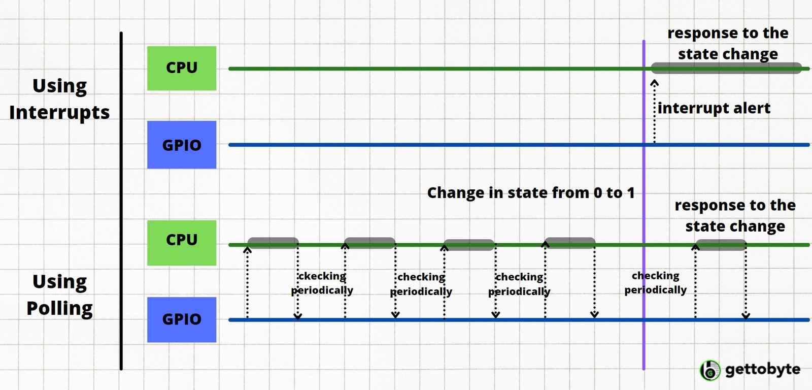
Something similar happens in the embedded system. If the operation requires the change in state i.e., from 0 to 1 or 1 to 0, the system needs to check the status periodically.
This is what happens in polling. It keeps on checking the GPIO values at frequent intervals. But this is a tedious process and consumes lots of power. If the checking interval is long, then there may be a lag between occurrence and detection, thus leading to a chance that it may miss the chance to detect the change in state.
Now let’s see another approach of the same example. Instead of standing beside the machine for 20 minutes, if you set a timer or alarm for 20 minutes and simultaneously do another task until the alarm rings, making you alert that clothes have been watched.
This is how exactly interrupts work. Now instead of checking periodically the change in state, when the change is encountered, the interrupt sends the signal to the CPU and the CPU immediately suspends the ongoing task (by storing the current state), process on the interrupt signal, and after completion, resumes the suspended task.
There are two types of Interrupts:
- Attached Interrupts:
An interrupt signal generated by an external device attached to the IRQ (Interrupt Request) pin to the MCU is called attached interrupts. When the relevant state change occurs, an interrupt request is sent to the IRQ pin, which alerts MCU’s interrupt controller.
- Peripheral Interrupts:
Interrupts from the on-chip peripherals like internal timer, GPIO lines, etc., are referred to as peripheral interrupts. The interrupt request is directly sent to the interrupt controller.
Here the interrupt controller just passes the signal to the CPU for the process. In case of multiple interrupts, signals are sent to the CPU based on relevant priorities.
One interesting thing to be noted here is that it immediately alerts the MCU when the change occurs and quickly switches to the requested processing. This rapid responsiveness is referred to as real-time processing.
Vector Table & RESET
The CPU starts its work after reading the first command from memory. But here an interesting question arises, where does it get to know about the address of the first command? The MCU reset button (raise reset signal when power on/off), reinitializes the value of the program counter, which stores the starting address of the first command to begin the process.
Now here two design pattern is followed for getting the initial address:
- Static Start Address Mode:
In this mode, the CPU always starts its command execution (when reset is called) at the same fixed address. Typically, the starting address is 0, however, if you want to start from a different address, simply place jump instruction at address 0 referring to CPU from where to start.
- Vector Reset Mode or Variable Start Address Mode:
In this mode, the CPU reads the start address from a reference table called vector table and correspondingly goes to that address for the execution.
Vector Table has a special area in the memory where the address of various commands and processes are stored. One such memory byte in the table holds the reset command where the memory address is stored for the first command. When the reset occurs, the CPU goes to that byte, reads the address, jumps to the stored address, and executes the first command.
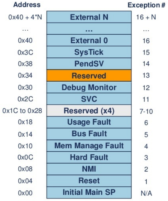
Let’s understand more about the vector table. Since the table consists of many commands, hence other address values, which tell the CPU where to go when handling the execution and where to go when an interrupt occurs.
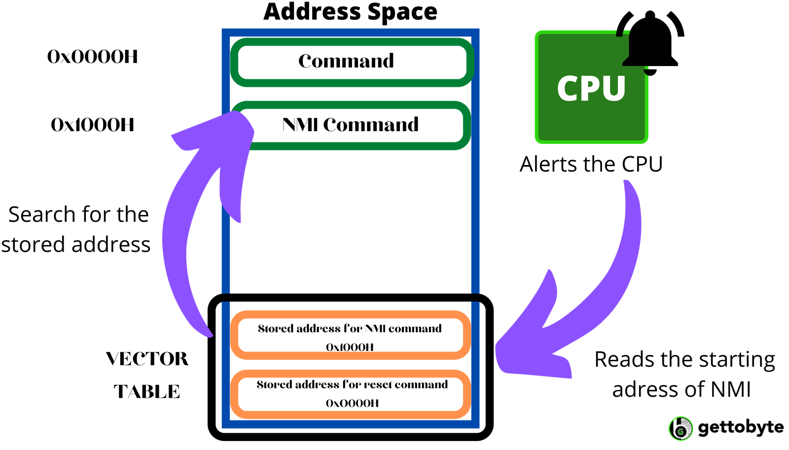
Consider an example as shown in Fig.6, showing a process involving non-maskable interrupts (interrupts which cannot be ignored by the CPU, also known as NMI, while CPU can ignore maskable ones).
Here first NMI occurs, and the CPU gets an alert. The CPU then refers to the vector table searching for the memory byte storing the NMI command for finding out the address, and finally reads and executes the NMI command by going to that address.
Conclusion
Let’s sum up the entire thing in a process flow.
- The MCU consists of various pins; some of them are GPIO used for both input and output processes along with various other operations.
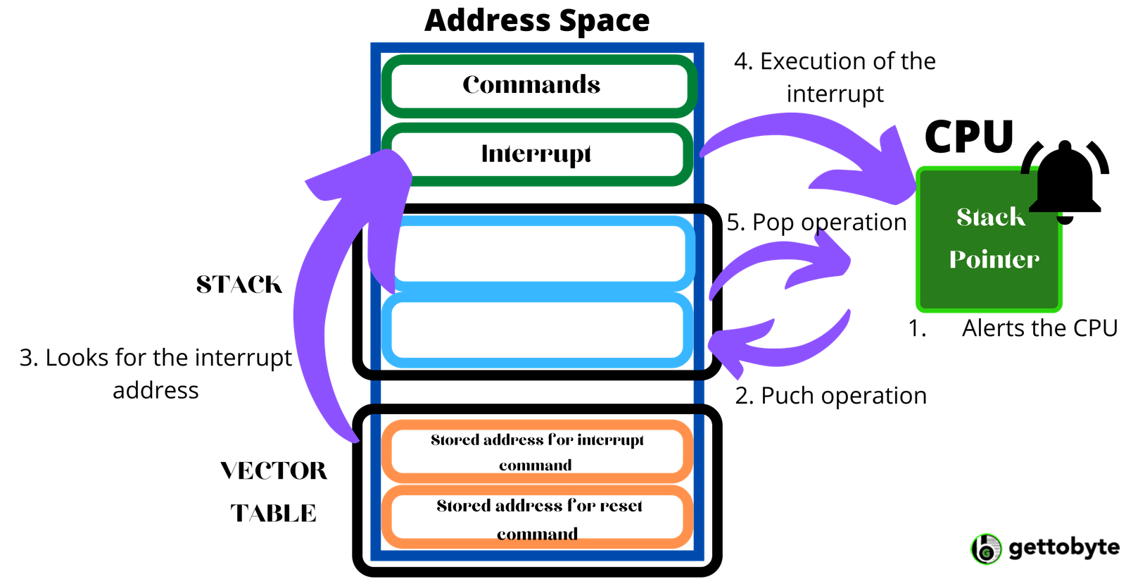
- When the CPU receives an interrupt alert, it saves the current states of the execution going on so it is easy to resume after the interrupt command is over. The data is saved in the stack manner using a stack pointer that contains the address of the topmost data state.
- CPU then loads the interrupt command by the address value from the vector table and then executes the interrupt command.
- A similar kind of procedure is followed in case of reset command and also when an error is encountered by the CPU.
- In the case of WDT, the CPU will shut down the commands (as the execution gets hung).
- After the execution of interrupts and WDT, the CPU resumes the task, after the return command tells the CPU to pop out. Here, the entire execution is stacked, so the CPU itself knows the push, pop execution.
Reference
- https://www.renesas.com/us/en/support/engineer-school
- https://microcontrollerslab.com/what-is-interrupt-vector-table/
- https://commons.wikimedia.org/wiki/File:Serial_vs._parallel_transmission.svg
