Overview
Welcome to Peripheral Control using AUTOSAR MCAL driver. In this blog, we’ll learn how to control PWM signal generation with variations of different duty cycles and frequencies.
What is PWM ?
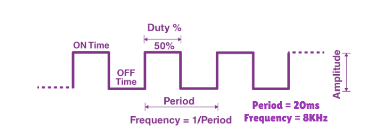
–> PWM (Pulse Width Modulation) is a technique used to generate analog-like signals by rapidly switching a digital output on and off. This creates a square wave signal with adjustable pulse width—the duration that the signal stays high (1) in each cycle.
Key PWM Measurements
Duty Cycle: The percentage of time the PWM signal is high within one cycle.
- Formula: Duty Cycle=On Time/Total Period×100%
- Effect: A higher duty cycle means a greater average output voltage, increasing the power delivered to the load. For example, increasing the duty cycle makes an LED brighter or a motor run faster.
Frequency: The number of PWM cycles per second, measured in Hertz (Hz).
- Formula: Frequency=1/Period
- Effect: Higher frequencies allow for smoother control in applications like audio signals or servo motors. However, excessively high frequencies may cause power losses due to switching inefficiencies.
Period: The total time of one complete PWM cycle, which is the inverse of frequency.
- Formula: Period=1/Frequency
- Effect: The period sets the overall timing for the PWM waveform. A longer period (lower frequency) makes each pulse longer, while a shorter period (higher frequency) allows for rapid switching. The period directly impacts both frequency and duty cycle calculations.

Getting Started
We are going to move toward the embedded software understanding of PWM frequency and duty cycle modulation, as per requirement, under the AUTOSAR MCAL standards, according to our DIY project statement. Make sure to follow the steps keenly and if any suggestion is invoked, please submit it on our community forum.
Step 1: Cloning the Repo from our GettoByte Github
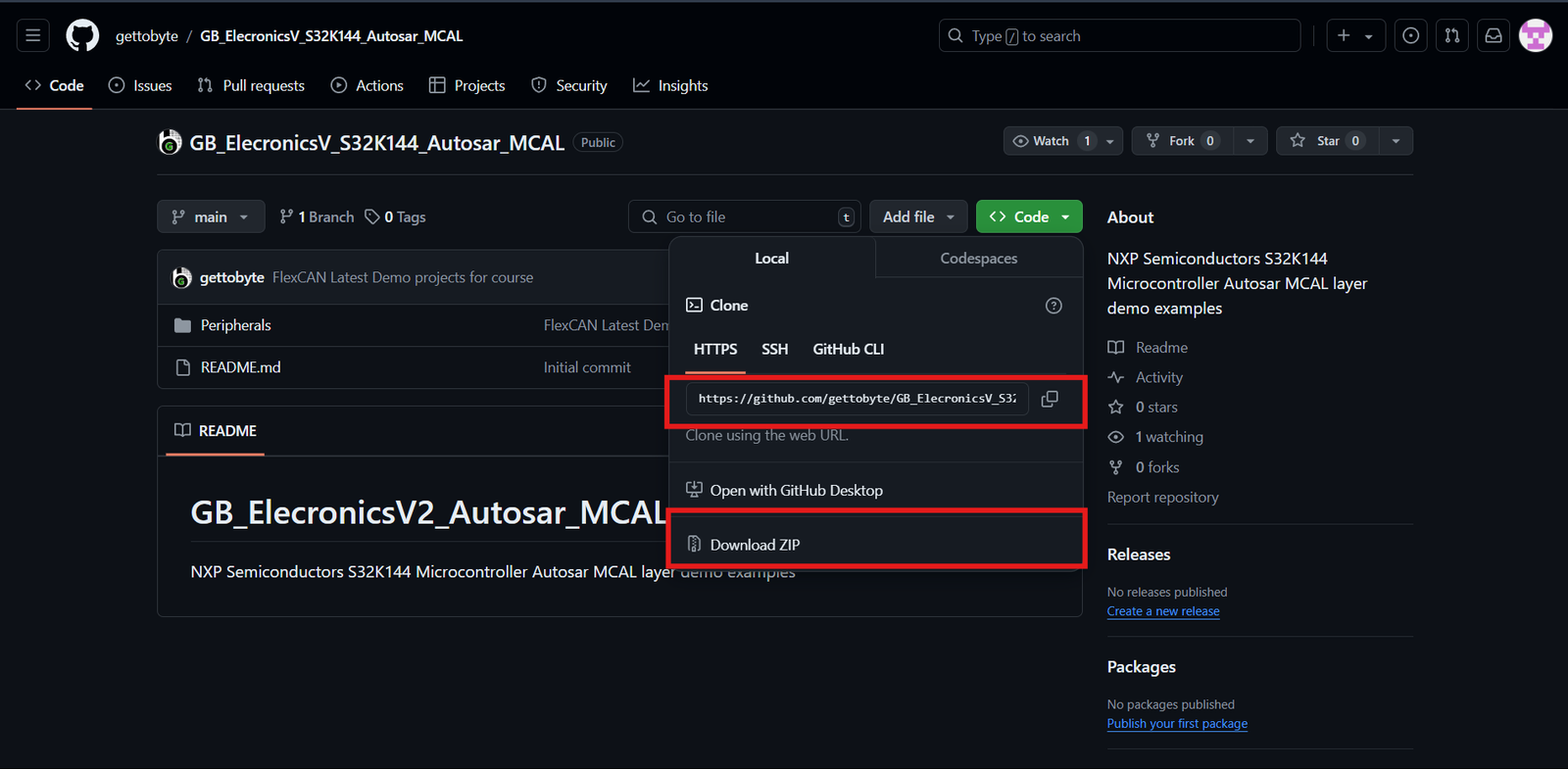
Download the ElecronicsV board Demo codes from the GitHub Repo of Gettobyte Technologies. If you have installed the Git, then one can clone the repo. Otherwise, one can download the repo by its zip file.
For cloning the repo, you can directly download it as a .zip file and extract it, else you can also use Tortoise Git to extract the files.

Step 2: Opening the cloned repo in S32 Design Studio
After getting the repo, now we are going to open the GitHub repo Example projects in S32 Design Studio. Make sure that you have downloaded the S32 Design Studio 3.4 and S32K1 RTD package versions 1.0.0 and 1.0.1 which we have stated in the tools installation.
Follow the below steps mentioned in slider to Open the Example projects in S32 Design Studio.
Step 3: Building the specific code
In Project Explorer, you can see all the files generated and included for the project but our main focus is on the .mex file which contains all portions of peripheral and MCU-related information. You can directly debug and run the code through the debug option.
To understand the complete explanation of the .mex file and how these different peripherals have different parameters thorough which we can generate our required result, you can follow the details on the courses link mentioned.
Code and Explanation
Breaking down the code
					#include "Mcal.h"
#include "Clock_Ip.h"
#include "IntCtrl_Ip.h"
#include "Port.h"
#include "Pwm.h"
- Declaration of important and used header files where
- “Mcal.h” is the header for MCAL standards
- “Clock_Ip.h” is the header for Clock configuration.
- “IntCtrl_Ip.” is the header for InterrupHandling.
- “Port.h” is the header for Pins and Port configuration.
- “Pwm.h” is the header for PWM configuration.
					volatile int exit_code = 0;

/* User includes */
void FTM_0_CH_0_CH_1_ISR(void);
void FTM_0_OVF_ISR(void);
#define channel0 0
#define channel1 1
#define instance0 0
2. Macro Definition where instance and channel of FTM are redefined with custom names. As well as the inclusion of external ISR from InterruptHandller files.
					Pwm_OutputStateType pwm_signal_state;
void pwm_callback(void)
{

	// returns the output state of PWM signal whether high or low
	pwm_signal_state = Pwm_GetOutputState(channel0);

}
3. This declaration is for the Callback Function of FTM. This callback is called when FTM pushes notification which is enabled.
					void TestDelay(uint32 delay);
void TestDelay(uint32 delay)
{
   static volatile uint32 DelayTimer = 0;
   while(DelayTimer<delay)
   {
       DelayTimer++;
   }
   DelayTimer = 0;
}
4. Function prototyping for a delay function that counts the parameter and decrementing it.
					uint16_t pwm_duty_cycle(uint8_t duty_cycle_percent)
{

	uint16_t duty_cycle = ((32768 * duty_cycle_percent)/100);

	return (duty_cycle);

}
5. Function prototyping for an input to percentage duty cycle conversion.
In NXP S32K144, the Duty cycle is taken in a range of 0x0000 to 0x8000. 0x0000 means 0% duty cycle and 0x8000 means 100% duty cycle. Therefore, our conversion is referencing around 32768 (= 0x8000).
					/*************Clock Configuration for MCU**************************/
	Clock_Ip_StatusType clockStatus;
	clockStatus = Clock_Ip_Init(&Mcu_aClockConfigPB_BOARD_InitPeripherals[0]);
	while (clockStatus != CLOCK_IP_SUCCESS)
	{
		clockStatus = Clock_Ip_Init(&Mcu_aClockConfigPB_BOARD_InitPeripherals[0]);
	}
	/* Busy wait until the System PLL is locked */
	while (CLOCK_IP_PLL_LOCKED != Clock_Ip_GetPllStatus());
	Clock_Ip_DistributePll();
	/*******************************************************************/
6. Function for clock configuration and initialization to CPU and different peripherals.
					/* Initialize all pins using the Port driver */
	Port_Init(NULL_PTR);
7. Function for MCU Port initialization, without this function pins of the microcontroller will be settled for usage.
					/* Install and enable interrupt handlers */
	IntCtrl_Ip_InstallHandler(FTM0_Ch0_Ch1_IRQn, FTM_0_CH_0_CH_1_ISR, NULL_PTR);
	IntCtrl_Ip_EnableIrq(FTM0_Ch0_Ch1_IRQn);

	/* Install and enable interrupt handlers */
	IntCtrl_Ip_InstallHandler(FTM0_Ovf_Reload_IRQn, FTM_0_OVF_ISR, NULL_PTR);
	IntCtrl_Ip_EnableIrq(FTM0_Ovf_Reload_IRQn);
8. Function for ISR enablement and linking it to their corresponding InterruptHandler.
- FTM_0_CH_0_CH_1_ISR: This ISR is for both channels 0 and 1 of FTM 0.
- FTM_0_OVF_ISR: This ISR is for the detection of counter overflow before a reset.
						/* Initialize all data structure and function of PWM */
	Pwm_Init(&Pwm_Config_BOARD_InitPeripherals);
9. Function for PWM initialization where the passed parameter is the structure of defined requirements in the .mex file.
Pwm_EnableNotification(channel0, PWM_BOTH_EDGES);
8. This function is to enable the callback function on both edges(falling edge and rising edge) detection of PWM for channel 0 only.
						Pwm_SetDutyCycle(channel0,pwm_duty_cycle(56));
	TestDelay(700000);

	Pwm_SetPeriodAndDuty(channel0,40000,pwm_duty_cycle(50));
	TestDelay(700000);
9. Here, we have two different functions for PWM output control.
- Pwm_SetDutyCycle()
- Parameter: 1st is the ChannelID and 2nd is the Duty Cycle.
- Work: It adjusts the duty of the ChannelD passed as a parameter.
- Pwn_SetPeriodAndDuty()
- Parameter: 1st is the ChannelID, 2nd is period and 3rd is duty cycle.
- Work: It adjusts the duty cycle and period of the ChannelID passed as a parameter.
- Pwm_SetDutyCycle()
						Pwm_SetOutputToIdle(channel0);
	TestDelay(700000);


	Pwm_SetOutputToIdle(channel1);
	TestDelay(700000);
10. These functions are for turning off the PWM signal generation at specified ChannelID.
						Pwm_SetPeriodAndDuty_NoUpdate(channel0,30000,pwm_duty_cycle(66));

	Pwm_SyncUpdate(instance0);
11. These functions are used where you want to pre-buffer a specific period and duty cycle before actually pushing it to change in pins.
- Pwm_SetPeriodAndDuty_NoUpdate(): This function takes the parameter as ChannelID, Period, and Duty Cycle.
- Pwn_SyncUpdate(): This is the function which pushes the pre-buffered setting of PWM which are settled by Pwm_SetPeriodAndDuty_NoUpdate. If this function is not called, then your pre-buffered setting will never be implied.
Conclusion
In this blog, we learned how to control PWM Output with variations in Duty Cycle and Period. You can also buffer your specific setting to be implied on a PWM generating pins by using functions like Pwm_SetPeriodAndDuty_NoUpdate.
Similarly, you can follow more sensor and module interface blogs for learning through practical implementation.
