About PORT Peripheral
In Microcontroller, there are number of pins through which it connects to outside world. For using these pins, we need some mechanism by which we can refer the pins of MCU and then some settings have to be done which decides how those pins have to be used. As when starting with microcontroller’s, using and configuring its pins is one of the first step that we have to do. And this thing is handled by PORT peripherals in microcontroller.
So, if to conclude, PORT peripheral is used to refer the pins of microcontroller by some symbolic names and to configure/initialize them on how they have to be used.
In some microcontroller’s this PORT peripheral is referred as Alternate Pins functions as well. Like in the case of Atmega 328 Microcontroller which is their in Arduino Uno boards, we have Alternate Port Functions through which pins of Atmega328 are configured for their operation. In the case of highly popular ARM Cortex CPU, STM32F103 MCU their also we have Alternate Function I/O through which pins of STM32F103 are configured for their operation. Taking another example of Automotive Development Board ElecronicsV3, which has S32K144 MCU, it has PORT peripheral through which its pins configuration is done.
Now as we have got the overview about PORT peripheral lets dwell into its functional concepts.
Let’s divide these concepts in 2 parts:
- Referring of MCU pins
- Parameters for Microcontroller pins
Referring of MCU pins
To use the Microcontroller, their are pins attached to it through which it connects to outside world and exchanges data. And to refer to these pins, their is concept of Ports in microcontroller. The pins of microcontroller are referred by grouping 32 pins in a single group. And these groups are called as Ports.
Port are named according to alphaphets, that is PORTA, PORTB, PORTC, PORTD and etc. Each Port can have max 32 pins of MCU. So MCU pins are referred as Port Pins as: PTA0-PTA31, PTB0-PTB31, PTC0-PTC31, PTD0-PTD31 and etc.
Now in a microcontroller, there can be individual registers for each MCU pin to configure its parameters, or their can be 16-bit or 32-bits GPIO peripheral regsiter, in which each bit represents the pin of the corresponding PORT.
Parameters of MCU Pins
To understand how MCU pins are configured, lets dwell into parameters of MCU pins. By parameters we basically mean the properties or features which are their in a MCU pin. And these can be broadly divided into 2 types:
- Port Pin Mode:
- Port Pin Direction:
Port Pin Mode
In a MCU there are number of peripherals like UART, I2C, SPI, GPIO and etc. The peripheral in which we want to use the corresponding pin is referred as mode of that pin. If we want to use a pin for GPIO peripheral, then we will configure its mode in GPIO. If we want to use it for UART peripheral, then we will configure its mode for UART peripheral.
Port Pin Direction
From the pins of Microcontroller, the data is either transmitted or received. So according to flow of data, we have to configure the pin’s direction. And these directions are:
- Input Direction:
- Output Direction:
- High Impedance Direction:
Apart from these 2, there can be other properties/features also like Port Pin Pull-up/down configuration, Port Driver strength and etc. Which can be subjective to MCU to MCU. So, we will dive into those features as we read about different MCU’s.
About GPIO Peripheral
GPIO is a peripheral in Microcontroller for using the MCU pins as transmitting and receiving of raw digital signals.
In the case of transmitting, it is said as Output pin and in the case of receiving it is said as Input pin. And by raw digital signals, we mean Digital High or Digital Low signal.
Concepts of GPIO Peripheral
To understadn more indepth about GPIO peripheral, lets divide its functional conepts in:
- Input Direction of GPIO pin
- Output Direction of GPIO Pin
Input direction of GPIO pin
In the case of Input direction, MCU pin can detect which type of external signal data is fed into it. That is whether High Digital signal (+5) or Low Digital signal (GND).
Like in the case of Switch, connected to MCU pin, as we press the switch, we send high signal and when we unpressed the switch we send low signal. So, this functionality is done via GPIO peripheral and by configuring it in input direction.
Also in Microcontroller, we can generate interrupt, as these digital High or Low signal is fed into them. These interrupts are called as Port Pin interrupts. The role of Input direction of MCU pin is also tilised in other communication peripherals as well where data is received by MCU.
Output direction of GPIO pin
In the case of Output direction, we can generate digital High (+5 or +3.3v) or digital Low(GND) signal from the Microcontroller pin.
Like in the case of LEDs, relays when we want to control some electric device by simple digital High and digital Low signals. Then output direction is used.
In the case of output direction, we can either generate Digital High signal or Digital Low signal
With Output direction there are some MCU to MCU features like pull up/pull down configuration and Drive strength
What is PORT Peripheral in NXP S32K1xx MCU's
The Port stands for Port Control and Interrupt (PORT) module which handles the port control, digital filtering, and external interrupt functionalities. It allows configuration for each pin of a microcontroller with respect to in which way pin has to be used.
–> Before going through technical details, let’s have a crisp gist of a what exactly PORT peripheral is. PORT peripheral is a role assigner through which we assign parameters to the pins of the microcontroller. Through parameters, we are referring to the peripheral functionality of pins. Each pin has its unique mathematically calculated value called PCR value. Using this PCR value(unique name), we tell PORT peripheral what properties are to be assigned to those pins. These properties or features can be understood in the “Features of PORT” section in detail but the most important property is assigning the mode of operation for a pin.
Number of Ports in S32K144
I/O multiplex signal excel sheet
Features of PORT peripheral in NXP S32K1xx MCU's
- PORT A – 18 Pins
- PORT B – 18 Pins
- PORT C – 18 Pins
- PORT D – 18 Pins
- PORT E – 17 Pins
–> You must have calculated the total of the above-mentioned pins and got 89 pins, then where are the rest 11 pins in our 100-pin package? These 11 pins are power pins.
- Port Control
- Pin Interrupt
- Digital Input Filter
–> Let’s understand each portion one by one, first is PORT CONTROL. Port Control as it clarifies its name this feature help in controlling the PORT and its pins.
- The first and most used port control feature is Pin multiplexing. Pin multiplexing is used to enable a specific peripheral functionality of a pin. A single microcontroller pin can be used for more than one peripheral, but at a time pin can be used for only one peripheral. So, it is the PORT peripheral responsibility to configure which peripheral MCU pin has to be used for. Peripherals like SPI, I2C, UART, GPIO, Ethernet etc. Below mentioned Alternatives are chip-specific, also for those who are thinking about why there is an 8:1 MUX only, this is because the S32K144 Port Register offers a 3-bit field for muxing the peripheral functionality of the pins. 3-bit can only give 8 possible values that are 0 to 7. This concept is register-level of microcontroller which is also mentioned after this section.

- After pin multiplexing, we are going to talk about the Pull Configuration. Pull configuration is an additional setting you can provide to the microcontroller pins. Pull Configuration helps you decide in which, logic level your pin should be when the pin is in the output direction, but no signal is outputted from it. This logic can be HIGH or LOW. To keep the logic level as HIGH we use a PULL-UP Configuration State which uses a resistor (called pull-up resistor) in series to connect that pin with the power supply voltage (Vcc) of the microcontroller. Similarly, to keep the logic level as LOW we use a PULL-DOWN Configuration State which uses a resistor (called pull-down resistor) in series to connect that pin with Ground reference. Now you must have a very crisp idea Pull Configuration of PORT peripheral. Let us move on to another exciting feature of the PORT module which is Drive Strength Configuration.

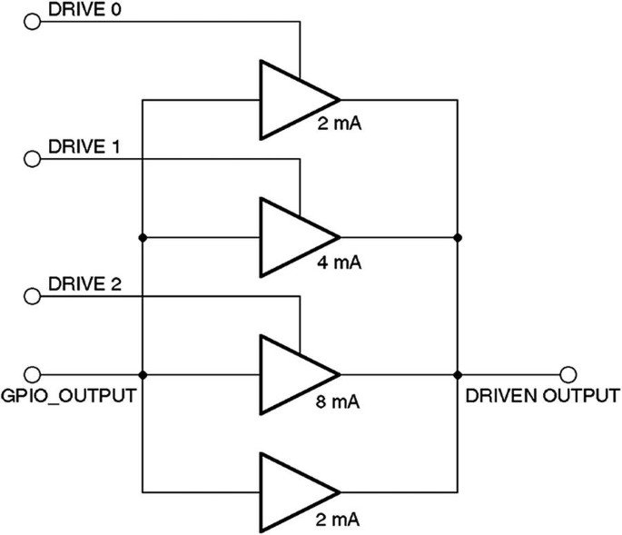
- Drive Strength Configuration is also a very great concept to learn and grasp. You might find this useful when you are using it for some heavy component driving (power electronics applications) where you need a high-power value from a pin rather than the usual power. This feature helps you control the amount of current that a microcontroller pin can provide when it outputs a signal. This feature has two options only which are HIGH Drive strength and LOW Drive strength. High Drive Strength implies a high current driving state on the specified microcontroller pin, the value of this high current can vary from microcontroller to microcontroller therefore read the datasheet for this current specification. And, similarly, Low Drive Strength implies a low current driving state on the specified microcontroller pin. What do we mean by high current driving state and low current driving state?

- Now the last feature that we are going to dwell on for the PORT peripheral is Passive Filter Configuration. Passive Filter Configuration is a bit complex feature to understand from the back end working of the development board, but let’s crisply summarize this so that you can understand basic applications and where to use this feature. Passive Filter Configuration provides analog filtration provided by the microcontroller. This filter value is provided by the datasheet of the microcontroller. Passive filter configuration uses only resistors, capacitors, and inductors to filter specific frequencies from a signal. Passive filters don’t require an external power source; they rely on natural resistive, capacitive, and inductive properties. There are multiple types of passive filter available but below mentioned is Passive Low Pass Filter(LPF).

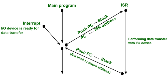
- This feature provides an interrupt functionality to each of the MCU pins for generating interrupts. By interrupt functionality we mean, it is a signal which can halt the current execution for some more prior work. you can take it as if you are enjoying your day seamlessly and suddenly your exam date sheet drops, It’s an external event that comes in during your usual day. Then that’ll be an interrupt that shifts your focus from current work to more prior work. Similarly, in the microcontroller world, we can create an interrupt for external events that come up to it and stop the usual execution flow of the MCU. In the context of interrupts in the PORT module, the external event is we mean some Digital High signal or Digital Low signal input to the pins of the MCU. Interrupt concept in Microcontroller is a great concept for learning which can be learned from this blog in detail. For now, let’s move forward.

–> In the last, moving toward the digital input filter, this concept might be too overwhelming, but we will try to brief you so that nothing leaves your keen learning of the PORT module.
- Let’s say you have a stable HIGH logic at the input pin, now you have you first enable the digital input filter and then load a Filter Length Value which is a kind of delay time. Now this Filter Length defines how long the input signal must driven LOW before the MCU can detect the falling edge. pulses that are shorter than this value will be absorbed and not acknowledged by MCU. there are more constraints behind this filter length but now you have enough knowledge about what a digital input filter does.
PORT-PERIPHERAL REGISTER
In this section, we’ll match the above learning features of the PORT Peripheral with Microcontroller Registers.

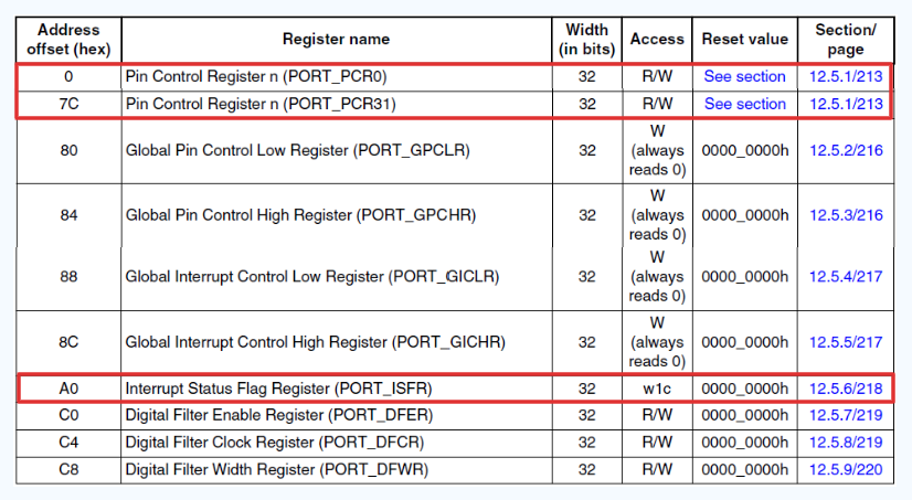
Above mentioned image demonstrates all the active registers in the PORT peripheral. But our main focus of interest is the Pin Control Register and Interrupt Status Flag Register. This contains our learned feature of the PORT Peripheral.

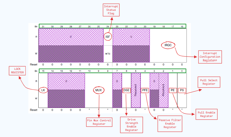
This is a PCR Register of a microcontroller pin. These registers are 32-bit each. Every Pin has its very own PCR register through which different features of that specific pin are configured. It’s time to break down the complete register bit by bit for better understanding.
- Starting from the 0th bit, this bit is the PS(Pull Select) bit. PS bit sets the type of pull configuration you want to apply to the specific pin. As this is a single bit, it can only have two values, 0(Internal Pullup Register) and 1(Internal Pulldown Register). This bit only reflects effects when the PE bit is set.
- 1st bit, PE(Pull Enable) bit is used to enable/disable Pull Configuration to the specific pin. Being a single bit, possible values are 0(Pull Configuration Disabled) and 1(Pull Configuration Enabled).
- 2nd and 3rd bits are reserved.
- 4th bit, PFE(Pass Filter Enable) is for enabling/disabling Passive Filter Configuration on the specific pin. This is also a single bit, possible values are 0(PF disabled) and 1(PF enabled, only if the pin is configured as input).
- 5th bit is also reserved.
- 6th bit, DSE(Drive Strength Enable) is also for enabling/disabling Drive Strength Configuration on the specified pin. This is again a single bit, resulting in values that are 0(DS enabled only if the pin is configured as Digital Output) and 1(DS disabled only if the pin is configured as Digital Output),
- 7th bit is also reserved.
- 8th-to-10th bit, MUX(Pin Multiplexing Control) is a function used for peripheral functioning multiplexing where you can assign a single peripheral function out of all available options. As this is a 3-bit field, possible values are 0-7 where 0 is for Pin Disabled, 1 is for GPIO and the rest of the is chip-specific functionality.
- 11th-to-14th bit are also reserved
- 15th bit, LK(Lock Register) which helps in securing the unwanted changes in pin functionality configuration. This 1-bit provides 2 values, 0(Does not lock the 0th to 15th bit of this register) and 1(Locks the 0th to 15th bit of this register and this lock gets revoked after a system reset).
- 16th-to-19th bit, IRQC(Interrupt Configuration) helps in enabling the different types of interrupt for specific pins. This is a 4-bit field that gives 15 variable combinations. Below is mentioned that which combination enables which type of interrupt with ISF.
- 0000 Interrupt Status Flag (ISF) is disabled.
- 0001 ISF flag and DMA request on rising edge.
- 0010 ISF flag and DMA request on falling edge.
- 0011 ISF flag and DMA request on either edge.
- 0100 Reserved.
- 0101 Reserved.
- 0110 Reserved.
- 0111 Reserved.
- 1000 ISF flag and Interrupt when logic 0.
- 1001 ISF flag and Interrupt on rising edge.
- 1010 ISF flag and Interrupt on falling edge.
- 1011 ISF flag and Interrupt on either edge.
- 1100 ISF flag and Interrupt when logic 1.
- 1101 Reserved.
- 1110 Reserved.
- 1111 Reserved.
- 20th-to-23th bit is also reserved.
- 24th bit, ISF(Interrupt Status Flag) is used to detect the generation of interrupt on the specific pin. Being a 1-bit field, possible values are 0 (Configured Interrupt is not detected) and 1 (Configured interrupt is detected).
Conclusion
We are glad to see you here. If you are reading then you must have completed the learning of PORT peripheral in S32K144. You can now have very brief control over PORT peripherals where you know every functionality offered by S32K144 on their microcontroller as well as you know the bit-level understanding about how and which registers are meant to be monitored in a debugging process.
Feel free to connect us over our community support for any queries and give your important suggestions over this blog.
