
Prerequisites for PDB of ADC
What is the PDB?
The PDB is a powerful peripheral in microcontroller’s designed to provide controllable delays and trigger events based on specific conditions for ADC peripheral. Those control delays and trigger events allows us to get ADC Data, making it valuable for applications requiring accurate timing or synchronization.
// In this elaborate following things:
Point to be learned:
- Q: What do we mean by controllable delays?
A: Controllable delays refer to the ability to set specific time intervals in a system to control when certain actions or events occur. It provides you with flexibility, configurable time delay, and precision. - Q: What do we mean by trigger event?
A: A trigger event is a signal(which can be external or internal) that prompts the system to begin a predefined action or series of actions. - Q: What and which specific conditions we mean here?
A: Configurable delay can be a counter-based delay, timer-based delay, or PWM-based delay. If we talk about PDB, here we use counter-based delay which involves using a hardware counter that increments or decrements based on a clock source. When the counter reaches this value, an event (such as a trigger or interrupt) is generated. And talking about the trigger event can be also classified into internal or external triggers, it is quite self-explanatory that if a trigger is received from a physical pin of the MCU then it is considered an external trigger and if triggers are initiated inside the MCU then it is called software trigger.
- Q: What do we mean by controllable delays?
Why is This Important?
Understanding how to use the PDB effectively can greatly enhance your control over ADC operations. Whether you’re working on a high-precision measurement system, synchronizing multiple ADCs, or simply improving the timing accuracy of your applications, the PDB offers the flexibility and precision you need.
How does PDB Peripheral works?
///// In this explain the relation of working of PDB peripheral.
- Q: How does PDB generate delays
A: As explained before, PDB works on a counter-based delay where we can specify the value of the counter. When the counter reaches this value, it will be reset back to zero. This counter register is labeled as “Modulus register (PDB_MOD)”. Let’s see how you can get a perfect modulus value for your desired requirement.
Example: Peripheral(PDB) bus clock is 48MHz(this can also be modified in the clock configuration tool) and before moving to modulus calculation you are always asked to set the value of pre-scalar and multiplication factor(these two can be in Status and Control Register (PDB_SC)). Prescalar value is used to divide the peripheral clock and set your desired value of clock for operation and multiplication factor as it defines its name, it is used for multiplying with prescalar division. Now we are considering the MULT(Multiplication factor) as 40 and PRESCALAR(Prescalar Divider) as 64.
PDB Period = ( (System Clock) / (Prescaler x Mult factor) )
PDB Period = (48 MHz / (64 x 40)) = 18750Hz
Now, we have a clock value for PDB and you can create multiple MOD values from this clock.If we need a counter value for 1 second, we just multiply the PBD Period with “n” second.
1 second = 18750 x 1 = 18750(MOD value)
2 second = 18750 x 2 = 37500(MOD value)
3 second = 18750 x 3 = 56250(MOD value)
NOTE: The maximum value for MOD is 65536(MOD register is 16-bit register), which means with my current setting I cannot create a 4-second counter value(4 seconds = 18750 x 4 = 75000 > 65536). In this case, you need to reconfigure the values of PRESCALAR and MULT. Q: Explain the concept of channels in PDB peripheral
A: In the Programmable Delay Block (PDB) peripheral, the concept of channels is central to its functionality. Each channel in the PDB is a separate entity that can be configured to trigger specific actions after a programmable delay. Each PDB channel is typically associated with a specific Analog-to-Digital Converter (ADC) block. For example, PDB0 will be linked to ADC0, and so on. PDB channels can be enabled or disabled independently. The concept of channels in the PDB provides flexibility in timing and synchronization, essential for applications requiring precise control over ADC conversions.Q: Concept of triggering in PDB by explaining terminologies like trigger event, trigger input, trigger source
A: The concept of triggering in the Programmable Delay Block (PDB) is essential for coordinating and controlling actions such as ADC conversions.
Trigger Input:
The trigger input is the physical or logical signal that the PDB monitors to detect a trigger event. This input can come from various sources like pulling a pin up or down, triggering through Bit Manipulation of register, and all.
Trigger Event:
A trigger event refers to the occurrence of a specific condition or signal that initiates an action within the PDB.
Trigger Source:
The trigger source defines where the trigger input originates.Just mention the concept of the triggering mechanism of ADC peripheral and how is it achieved through PDB
Relation of PDB delays with ADC peripheral
How does the PDB peripheral control the ADC peripheral
The Programmable Delay Block (PDB) includes a counter that compares its output to various preset digital values. When the PDB is enabled, a trigger input event will reset the counter and start counting. A trigger input event can be a rising edge detected on a chosen external trigger source, or it can be initiated by a software trigger.
For each channel, a delay determines the time between the assertion of the trigger input event to the time at which changes in the pretrigger output signal are started.
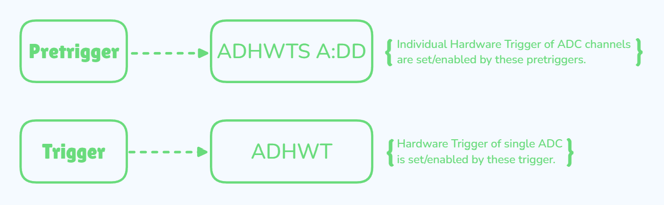
Each channel in the Programmable Delay Block (PDB) is linked to a specific ADC block. These pre-trigger outputs are connected to the ADC’s hardware trigger select. The role of the pre-triggers is to prepare the ADC block before the main trigger signal is applied. When the ADC detects a rising edge on the main trigger input, it starts the conversion process based on the settings and conditions established by the pre-triggers.
The pre-trigger outputs are used to specify which signal will be sampled next.
Delays can be independently configured using the channel delay registers, and pre-triggers can be enabled or disabled via the PDB Channel Pre-Trigger Enables. If the PDB Channel Pre-Trigger Output Select is cleared, the delay set in the channel delay register can be bypassed. In such cases, the pre-trigger output occurs immediately after 2 peripheral clock cycles following the trigger input event.
Triggering and it's types
Triggering refers to the signal that initiates an event or operation within a microcontroller. In the context of ADCs, a trigger signals the peripheral to start a conversion, measurement, or other action. In the context of ADC, we can say that Analog to Digital value conversion will start when ADC peripheral is triggered by some kind of signal. These Triggers can be generated internally by the microcontroller, or externally from external events or signals.
- /////explain the concept of pretrigger/trigger, and their differences.
Types of Triggering:
Triggering is sub-divided into 2 triggering that is Software Triggering(SWTrig) and Hardware Triggering(HWTrig):
- Software Triggering
Description: The ADC conversion is initiated by a software command or instruction.
How It Works: The application code sets a bit in a register to start the ADC conversion. This method is simple and requires software intervention to start the conversion.
Correlation: Software triggering means that an API provides a function to set or clear a bit to initiate the trigger. - Hardware Triggering
Description: The ADC conversion is initiated by an external hardware signal or event.
Correlation: Hardware triggering means that a physical event(eg. push of a button) or signal(eg. PWM, timer/clock) directly initiates the trigger.
Types of Hardware Triggers:- Timer Trigger: A timer generates periodic pulses to trigger ADC conversions at regular intervals.
- External Pin Trigger: An external event, such as a signal on a specific pin, can trigger the ADC. For instance, a signal from a sensor or another peripheral can start the conversion
- Software Triggering
You might wonder why we should use the PDB when we could simply start the ADC conversion with an if/else statement. For example, we could initiate ADC conversion when event X occurs, where X could be the press of a button or a PWM signal. While this approach is possible, it requires additional C code in your application or the nesting of interrupts between multiple peripherals. This adds to the CPU load, which is particularly problematic in time-critical and complex applications like motor control, where CPU loading can decrease motor efficiency.
By using the PDB, there’s no need to constantly monitor events with if/else statements or juggle multiple interrupts. Instead, you simply configure the PDB and let it handle the timing and triggering. This reduces CPU load, allowing for more efficient operation, especially in demanding applications.
Modes of Triggering:
Apart from the two types of triggering, triggering can be done in two different modes also:
One-Shot Triggering
In one-shot mode, the peripheral performs its operation (e.g., ADC conversion) once in response to a single trigger event. After the operation is completed, the peripheral stops and waits for another trigger to start a new operation.
Correlation: Lighting a fuse on a firework is a one-shot trigger. Once you ignite the fuse, the firework will launch and explode only once. After the event, the fuse cannot be reused; a new firework must be prepared for another show.
Continuous Triggering
In continuous mode, the peripheral continuously performs its operation at regular intervals, usually after each trigger event, until it is explicitly stopped. This mode is useful for applications requiring periodic or repetitive measurements.
Conclusion: Continuous triggering is a rotating sprinkler system. Once you turn on the sprinkler, it continuously waters the garden, rotating around and spraying water without interruption. The system keeps functioning as long as the sprinkler is turned on. To stop the functioning you have to turn off the system.
Combining Triggers and Modes
Here’s how different combinations of triggering and modes can be used:
Software One-Shot Triggering: The microcontroller starts an operation in response to a software command. After the operation is complete, it waits for another software command to initiate the next operation.
Code Analogy: This is like having the software trigger command placed outside theforloop. When the software trigger is executed (e.g., a function call), it initiates a single ADC conversion. ThereadValue()API inside theforloop will show the result of that single conversion. Till the software trigger command is outside theforloop,readValue()API will show the same result irrespective of changes in the ADC input channel.Software Continuous Triggering: The microcontroller uses a timer or counter to continuously generate triggers, causing the peripheral to perform its operation at regular intervals. This is useful for tasks like periodic data sampling.
Code Analogy: This would be like placing a continuous software trigger outside theforloop. But still, counter-linked with PDB peripheral counts continuously at the back end, and at the end of the counter software trigger bit is set and the counter is reset and restarted. As a result,readValue()will show updated values reflecting the most recent conversion data, allowing for continuous monitoring.Hardware One-Shot Triggering: An external hardware event triggers the operation once. For example, a button press might initiate a single ADC conversion.
Code Analogy: This would be like having no trigger set up outside theforloop cause these hardware triggers directly set/clear the trigger bit at the backend. When the hardware trigger is activated (e.g., by a physical signal), it initiates a single ADC conversion. ThereadValue()API inside theforloop will then show the result of that single conversion. You have to activate the hardware trigger again for each new conversion.Hardware Continuous Triggering: An external hardware signal continuously triggers the operation. For example, a pulse train from a sensor might repeatedly start ADC conversions at each pulse.
Code Analogy: This would be like setting up a hardware trigger to continuously initiate ADC conversions. When the hardware trigger is configured for continuous operation, it automatically repeat triggers conversions, andreadValue()will show the most recent conversion result each time it’s called, reflecting continuous data acquisition.
PDB Peripheral Modes of Operation with respect to S32K144 Microcontroller
//////Explain the PDB peripheral working scenarios with ADC peripheral. Explain what all ways are their to to use PDB for starting ADC conversion.
//////And then also tell what all option we are going to explore.
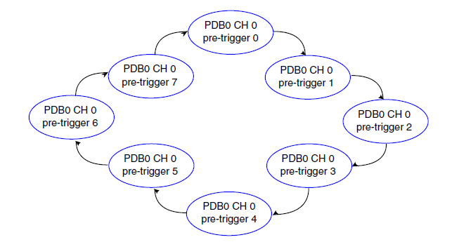
Purpose: Back-to-back operation in the PDB is designed to facilitate a sequence of ADC conversions with minimal delays between them. This mode is useful when you need to perform continuous or sequential measurements where each ADC conversion should trigger the next in a series without manual intervention or reconfiguration.
How It Works
Configuration:
- PDB Channel Pre-Trigger Back-to-Back Operation Enable: This specific bit in the PDB Channel Control register (CHnC1) is used to enable back-to-back operation for a given channel. When set, this enables the back-to-back mode for that channel, allowing it to automatically trigger subsequent channels without additional setup.
Trigger Sequence:
- Initial Trigger Event: When a trigger input event occurs (such as a rising edge on a selected trigger input source or a software trigger), it starts the PDB counter and initiates the timing sequence.
- Pre-Trigger Assertion: In normal operation, pre-triggers are used to prepare the ADC hardware before the main trigger occurs. However, in back-to-back mode, the delay set for the pre-trigger (channel delay register) is effectively bypassed.
Execution:
- Immediate Assertion: When the back-to-back mode is enabled, the pre-trigger output is asserted immediately after an acknowledgment signal (COCO bit of each channel acts as ACK when data is read from the register) is received, but with a fixed delay of 2 peripheral clock cycles. This ensures that the subsequent ADC conversion is triggered almost immediately after the completion of the previous one.
- Sequential Conversions: As each ADC conversion completes, it automatically triggers the next set of pre-triggers and triggers. This allows the ADC to continuously process data in a chain without the need for additional software intervention or manual reconfiguration.
Benefits:
- Reduced Latency: By eliminating the need for manual re-triggering and bypassing the pre-trigger delay, back-to-back operation reduces the latency between sequential ADC conversions.
- Efficiency: This mode is highly efficient for applications requiring continuous data acquisition, as it minimizes overhead and ensures a smooth, uninterrupted flow of data.
Back-to-Back Mode (Interchannel)
