


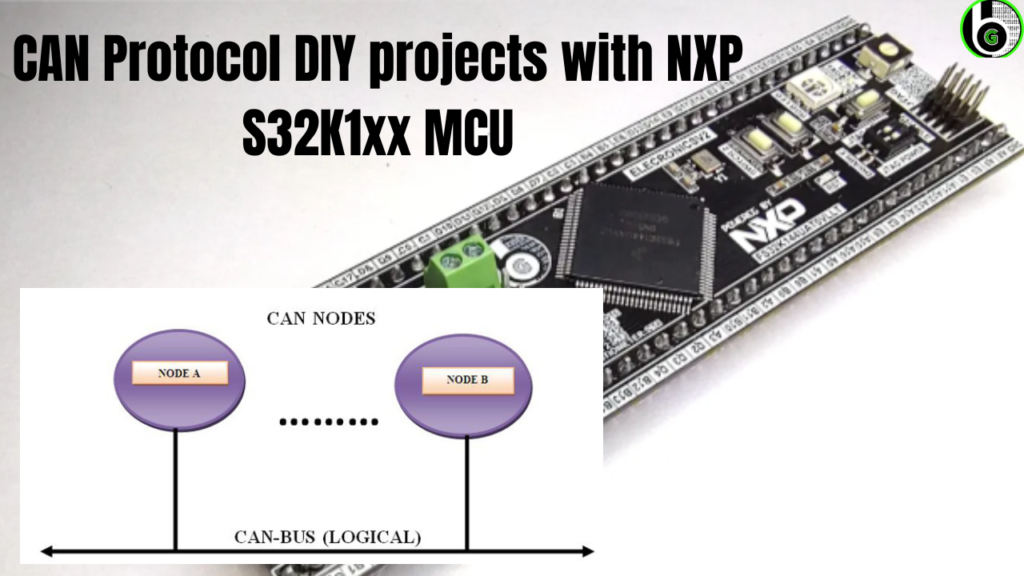
Getting Start with CAN Protocol using Automotive Microcontroller(S32K1xx)
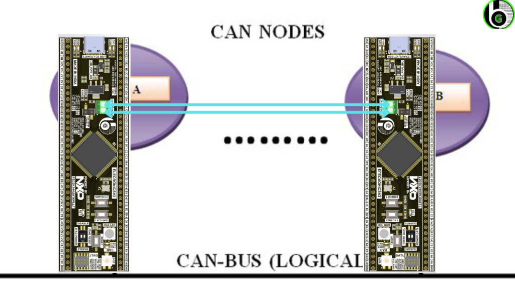
In ElecronicsV2 board, there is on Board CAN transceiver IC to do CAN bus communication and give reality to actual Automotive DIY projects.
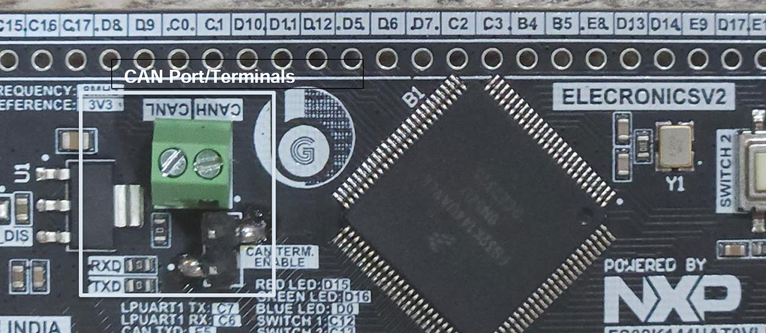
It has an onboard TJA150 CAN transceiver IC. For doing the CAN Communication, the board has on-board green screw terminals exposing CANH(PE5)
and CANL(PE4) pins of CAN 0 port.
Just Connect the CANH of one ElecronicsV2 with CANH of another Elecronicsv2 and similarly CANL of one ElecronicsV2 to CANL of another ElecronicsV2 board.
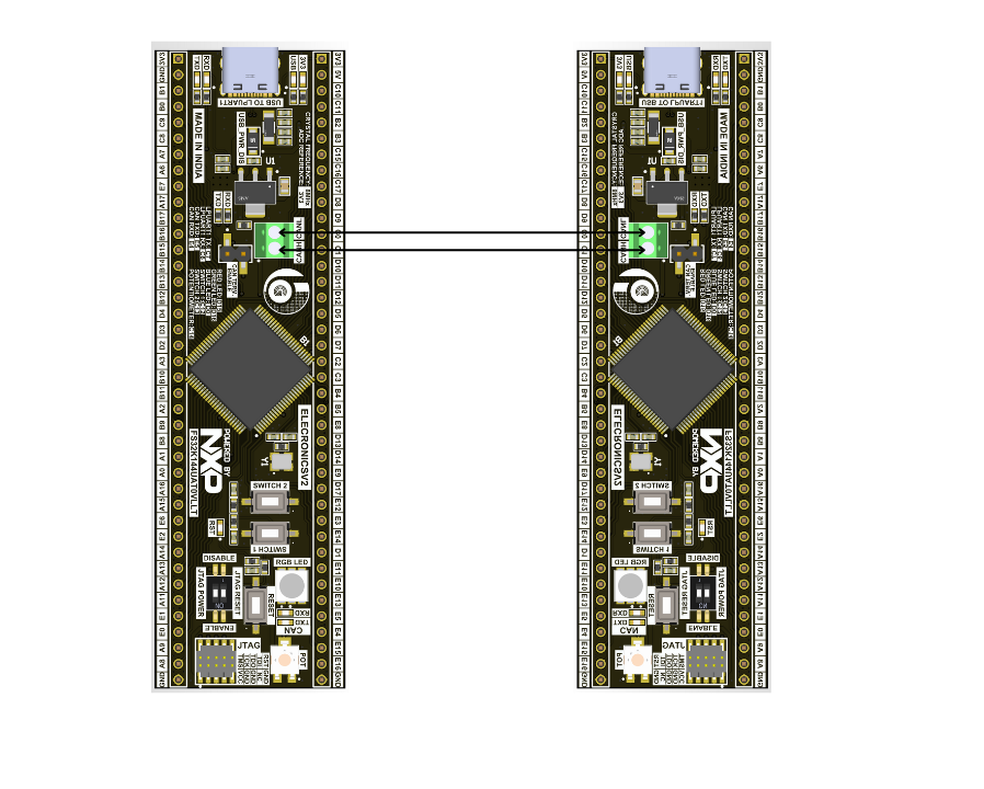
PS: Make sure you power the ElecronicsV2 via USB cable too. It has on board UART to USB Type C cable. For powering CAN transceiver IC, it needs 5V. Powering the board via external Debugger would provide only 3.3V. To activate the CAN transciever IC, it would require 5V that will be supplied by on board USB cable.
We are using ST7789 LCD screen for displaying the CAN messages. To know how to interface ST7789 LCD screen, refer to corresponding blog, Section Hardware Connections:
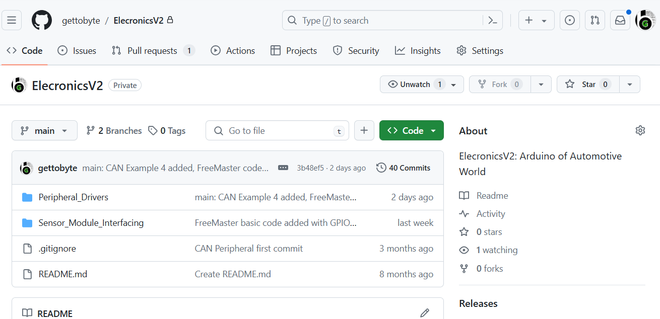
Once you get the access for it, you will ElecronicsV2 Repo on Github:
After Cloning the project, you can see its folder structure in your host Desktop/Laptop.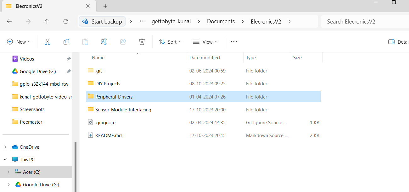
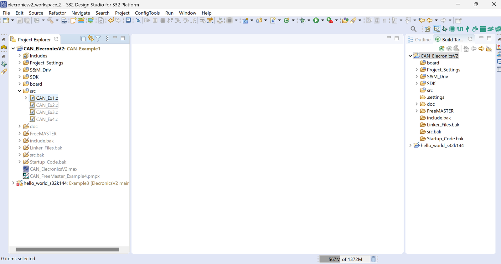
Now after you have cloned the project, navigate to Peripheral_Drivers -> CAN -> CAN_ElecronicsV2 and you will see an example project: CAN_ElecronicsV2. This is the our main demo project that we are gonna use and we will be opening it in S32 Design Studio 3.4.
P:S: Make sure in your S32 Design Studio 3.4, S32K1 RTM SDK v4.0.3: Software package is downloaded as it is instructed over here: Getting Started with S32 Design Studio Part 1 – Get To Byte, before opening the CAN_ElecronicsV2 project.
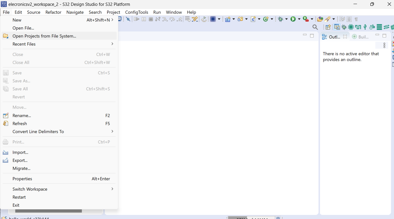
Now open the S32 Design Studio and we have to open the CAN_ElecronicsV2 project into it. So as to open this project in S32 DS, navigate to file->Open Project from File System. To know how to open the already developed project in S32 DS, refer to this blog: Getting Started with S32 Design Studio Part 1 – Get To Byte.
After opening the project, you can see it open in the project explorer of S32 Design Studio. Drop Down the Src folder and you will see main files of CAN_ElecronicsV2.
In the Project, you can see .mex file: CAN_ElecronicsV2.mex file. This is very important file, as this file opens the code configuration tool for S32K144 Microcontroller. To know more in depth about code configuration tool, checkout this blog: Getting Started with S32 Design Studio Part 2 – Get To Byte. Double Clicking on .mex will open the GUI based window, in which you can see components and sections to configure the peripherals of S32K144 Microcontroller.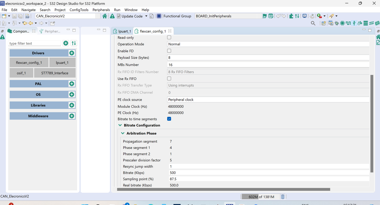
In our last blog FlexCAN Peripheral in S32K144, we have learnt the meaning of FlexCAN sections in Code Configuration Tool. Also in the Project, you can see number of files and folders. Don’t worry and don’t get overwhelmed with it. We will cover details of these folders in next blog, for now just move ahead.
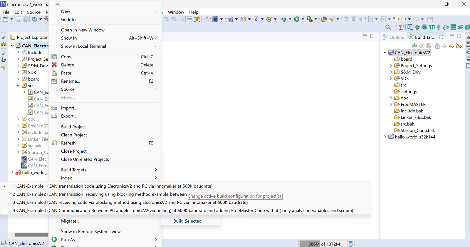
Now in This CAN Demo project, their are 4 examples:
- CAN_Example1: CAN transmission code via blocking method using ElecronicsV2 at 500K baudrate.
- CAN_Example2: CAN transmission & receiving using blocking method example between ElecronicsV2 and PC via innomaker.
- CAN_Example3: CAN receiving code via blocking method using ElecronicsV2 at 500K baudrate.
- CAN_Example4: CAN Communication Between PC and elecronicsV2(via polling) at 500K baud rate and adding FreeMaster Code with it (only analyzing variables and scope)
You can see these 4 example by Right clicking on Project and going to Build Configuration:
We are going to use CAN_Example 1 and CAN_Example 3. In CAN Example1: We are transmitting the data continously and in CAN Example3: we are waiting to receive the data at CAN0 port. We have configured the Message ID: 0x800 for both transmitting and receiving nodes.
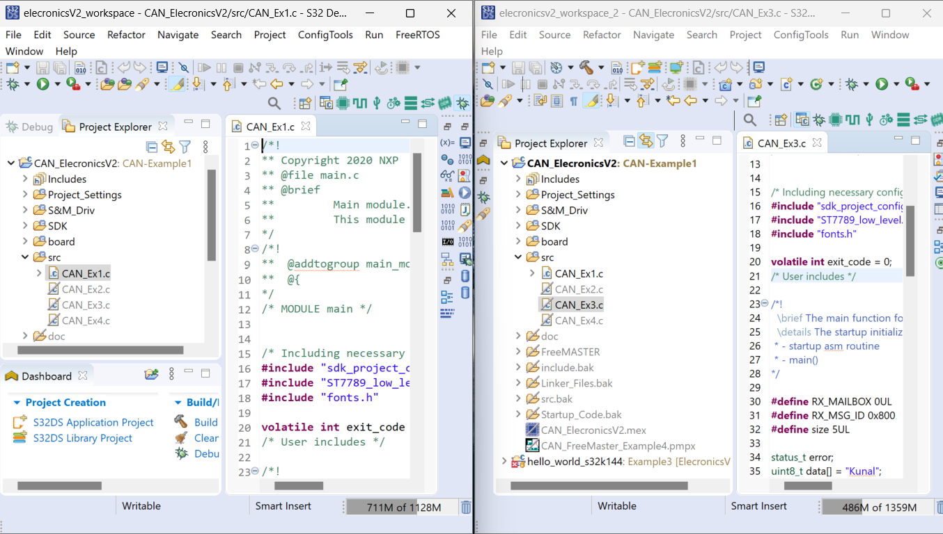
Now for Building the code, open the CAN_ElecronicsV2 project in 2 different workspaces. In work workspace open the Example 1 and in another workspace open the Example 3.
After that Build both the projects by clicking on the Project name and then going to Project Icon in Toolbar and click on Build the project. Project will start compiling(you can see building process in console view)).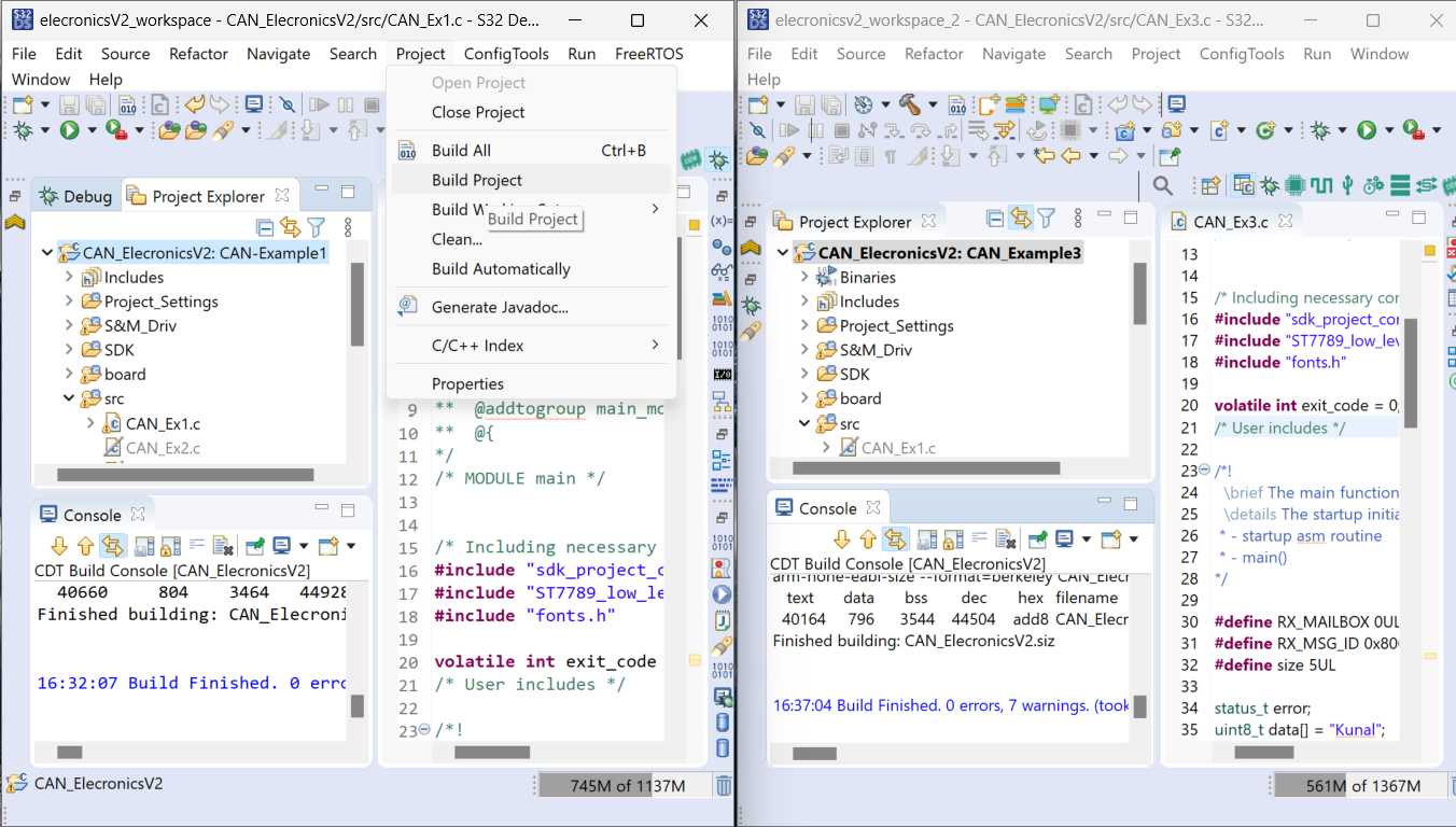
After Building the project as stated in above steps, you would be able to see the executable files of our example projects. Now we have to flash these executables files(.elf) in ElecronicsV2 Development Boards.
Okay so now we have Opened the CAN Demo projects in S32 Design Studio successfully and also compiled corresponding example projects successfully. Now we are gonna flash these examples project into the ElecronicsV2 Boards.
- For doing so, connect the ProBug Debugger with ElecronicsV2 Development Board by connecting JTAG-SWD 10 pin connector Present in ElecronicsV2 with JTAG SWD 10 pin connector present in ProBug Debugger via 10-pin Female to Female connecting wire.
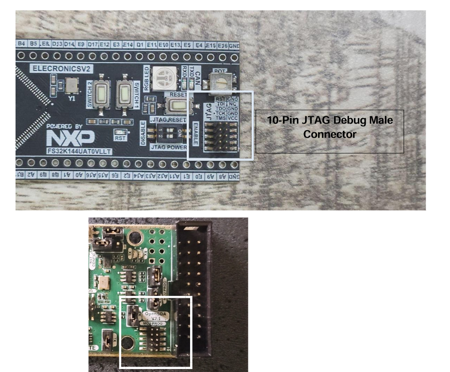
- If you are using latest ElecronicsV3 Development Board of S32K144 Microcontroller, it has on-board Jlink Debugger. So no need to connect any wires, just Connect the USB-to Type C cable and you are good to go.
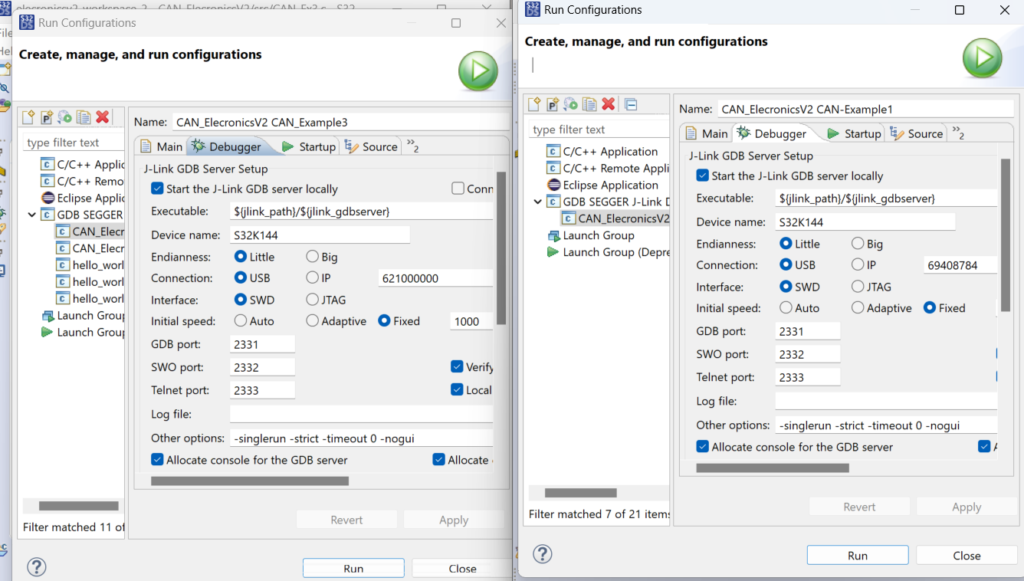
Now for flashing the project into ElecronicsV2. Click on Run-> Run Configurations. A Pop-up window like this will come up and click on GDB Segger J-Link Debugging and then Top icon of New Launch Configuration:
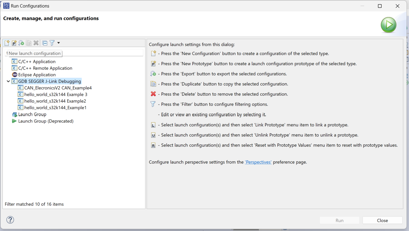
After clicking on New Launch Configuration. The Run Lunch Configuration would automatically be genrated for the Example project which you have selected in Project Explorer. I have here shown for Example3, same way Example1 Run Launch configuration would be generated.
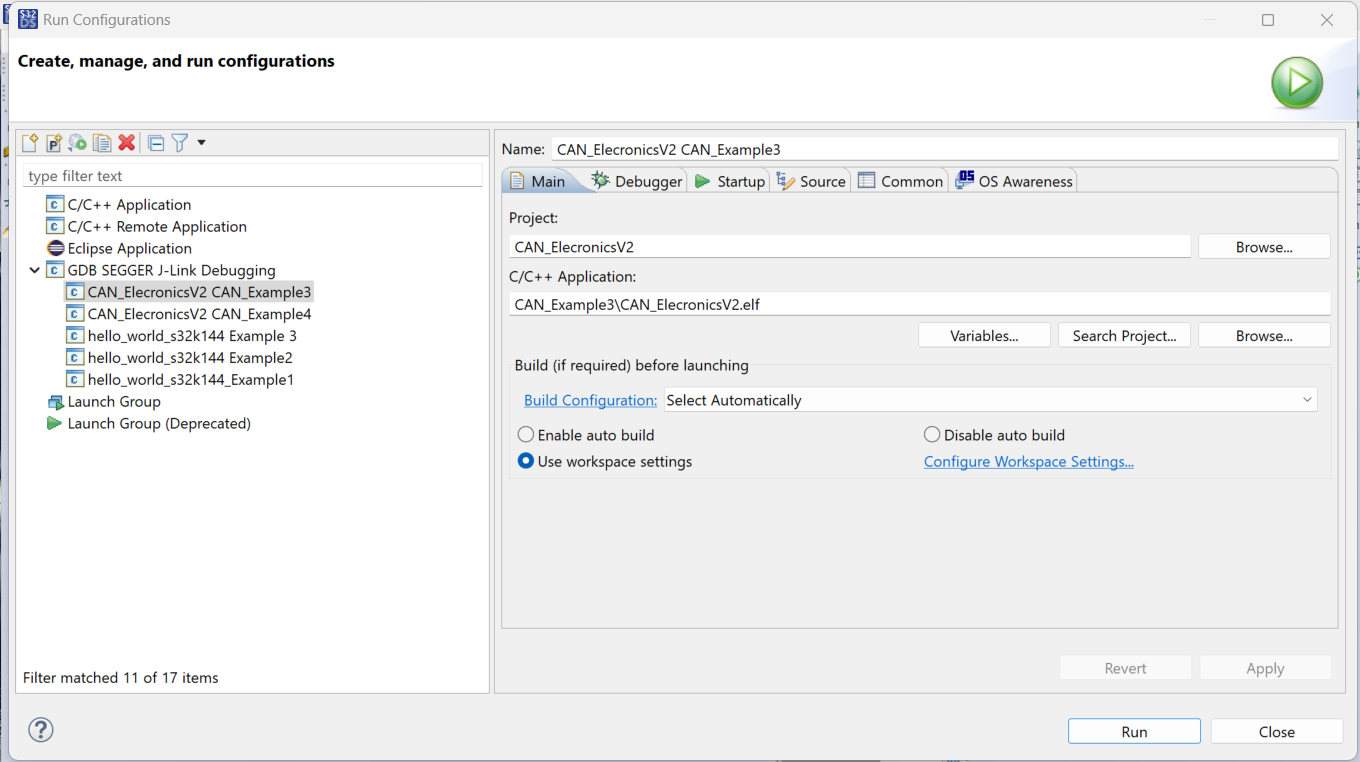
Following things should be take care:
- Make sure in main tab, you have browsed the C/C++ application with correct *.elf file. It should be of example project on which you are working, often many a times. Like here we are working on Example3, so CAN_Example3 should be wriiten in path. And CAN_Example1 for example1.
- In Debuggers tab, select the device name. Some time Device name is not automatically added. By Device Name we mean MCU name, which is S32K144.
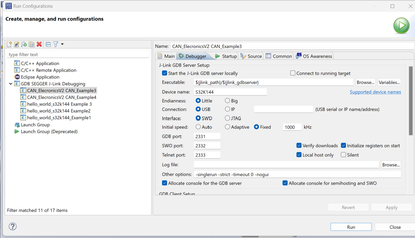
- In Debuggers tab, their is column with (USB Serial), adjacent to Connection Type. Write the Serial Number of Jlink Debugger which is connected to PC. As we would be connecting 2 ElecronicsV2 boards to same Desktop, so it means 2 Debuggers would be connected. So as to distinguish between these 2 debuggers during the flashing of elf file, we will configure the USB serial of corresponding Jlink Debuggers with corresponding examples which has to be flashed via them. To know the Serial Number of Jlink Debugger, connect the Jlink Debugger (whether ProBug Debugger or On -Board Debugger) and search for Jlink Commandor, a pop up will come into which you can find serial numbers:
- Also change the GDB port of any one configuration from 2331 to 2335. Otherwise their will be conflict in GDB server port, when we start the Run/Debug Configuration.

Now if you want to Debug the code and do step-by step debugging/analyzing of the code. All steps are same as done in Step 5. Just instead of Clicking on Run Configuration, we will click on Debug Configurations and similar pop-up and setting will come as we have done in Step 5.
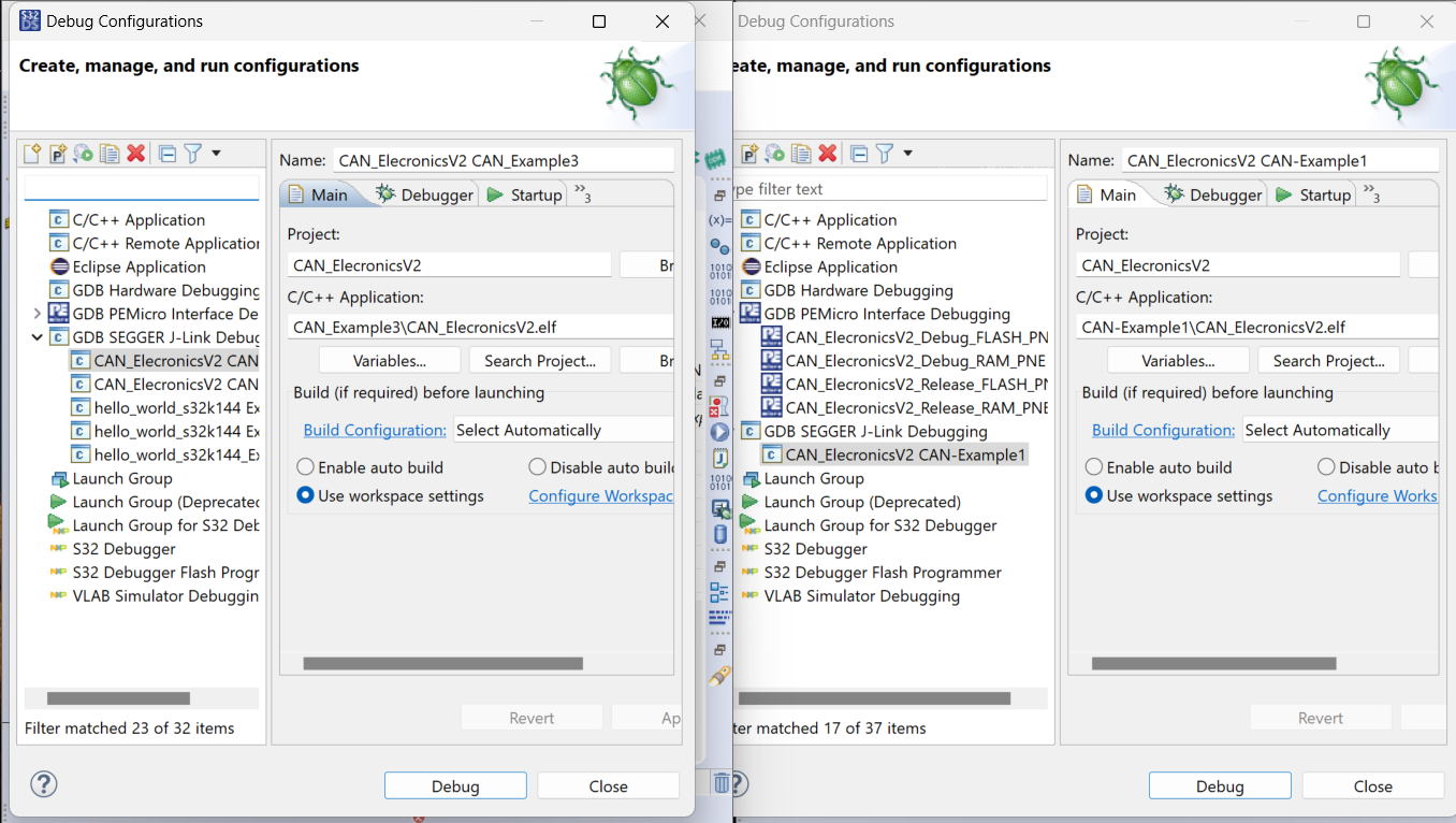
After that click on Debug and you will see that Debug window for both the Launches.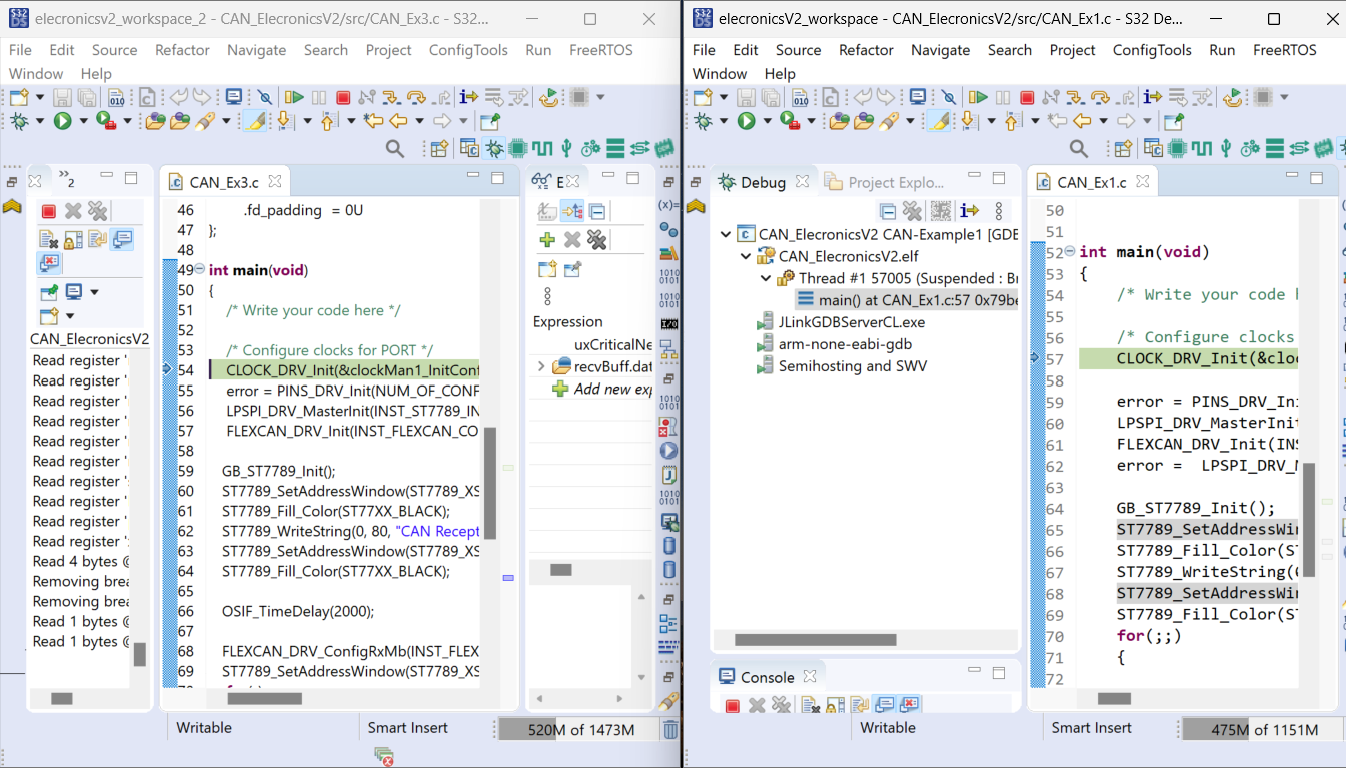
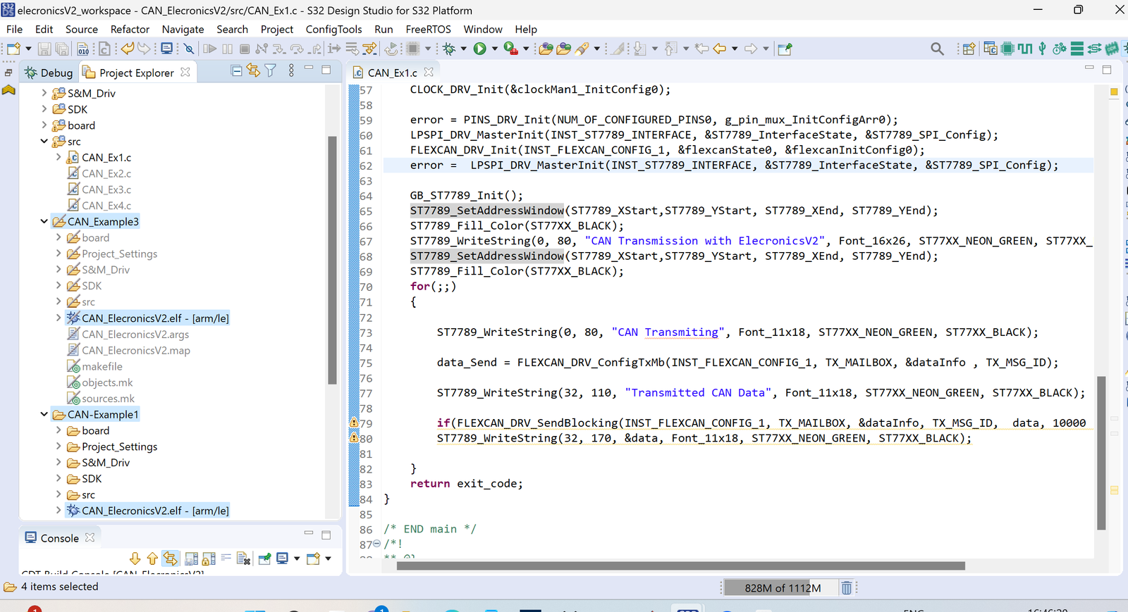
Now first let the CAN_Example3( which is our receiving code) Run and you will see on its LCD screen CAN receiving related messages will start coming. And also make a breakpoint on line number 82. When CAN will receive the data, it will stop at line no 82.
After that, Run the CAN_Example1( which is our transmitting code) Run and you will see on its LCD screen CAN transmission related messages will start coming.
And now you will see that when CAN_Example1 node transmitts the Data, CAN_Example3 node will stop at line number 82. And further you step down the CAN Example 3, the transmitted string will be printed on the screen.
To get better understanding and clarity of the Debug configuration, will recommend to watch the video, In which i have explained this thing in a better way.
You can also analyze different variable values and expression values in Debug Mode.