
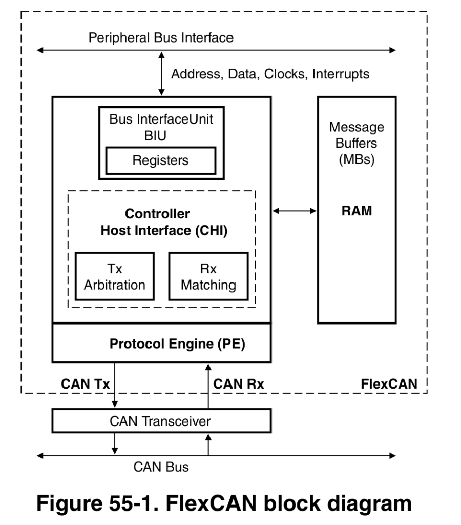
FlexCAN Module is a Microcontroller peripheral in NXP Semiconductors S32 series of microcontroller for doing CAN communication via CAN protocol. S32 series have number of microcontrollers, for understanding we are going to refer S32K144 microcontroller, as this blog series is specific to S32K144 MCU.

There can be multiple instances of FlexCAN module in a microcontroller. Like in S32K144 MCU it has 3 instances of FlexCAN module, whereas in S32K344 has 5 instances of FlexCAN module. By instance we mean, number of counts. So, in S32K144 we have 3 FlexCAN modules, meaning 3 communication channels of CAN be done via S32K144. In S32K344 we have 5 FlexCAN modules, meaning 5 communication channels can be done via S32K344.
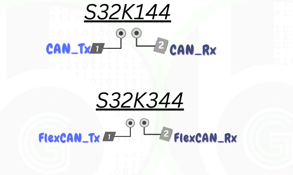
Now for doing CAN communication, FlexCAN module would be using CAN pins of the microcontroller to physically transmit and receive CAN data. The CAN pins are termed as CAN_Rx-CAN_Tx pins in the case of S32K144 MCU and FlexCAN_Tx-FlexCAN_Rx in the case of S32K344 MCU. CAN_Rx & FlexCAN_Rx for receiving pins and CAN_Tx & FlexCAN_Tx for transmitting pins.
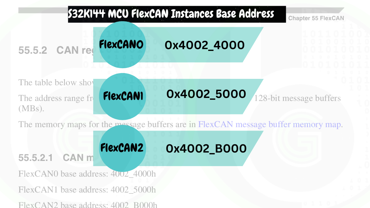
Each Instance of FlexCAN has their own FlexCAN peripheral registers. Which starts at mentioned address of microcontroller memory. These address are named as FlexCAN instance base address.
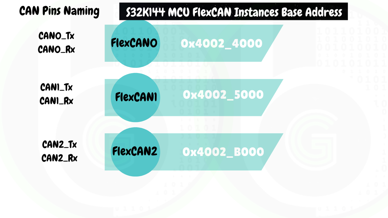
Now which pin to use via which instance is logically mapped as per numbering. FlexCAN0 would be using CAN0_Tx and CAN0_Rx pins. FlexCAN1 would be using CAN1_Tx and CAN1_Rx pins and so on.
Now further for each CAN instance there are number of pins available. Meaning let’s say we want to use FlexCAN module0 of S32K144 MCU. For that we will be using CAN0_Tx and CAN0_Rx pins. CAN0_Tx and CAN0_Rx pins can be mapped to number of pins of microcontroller. As shown in Figure

We have to set the alternate function registers of the microcontroller to configure the pin that we want to use for corresponding Instance. This pin configuration part is handled by Port Peripheral of the S32K144 Microcontroller.
For setting the speed of communication of FlexCAN module, we have to configure its clock and baurate settings. The Clock to FlexCAN module is fed from Clock peripheral of MCU and then FlexCAN module baudrate can be set by application as per their requirements.
- FlexCAN module implements the CAN protocol according to the ISO 11898-1 standard and CAN2.0B protocol specifications.
CAN 2.0B protocol specification defines the properties and features in CAN protocol (Standard CAN and Extended CAN) and ISO-11898-1 standard specifies how outgoing and incoming CAN data should be managed so that CAN properties are achieved.
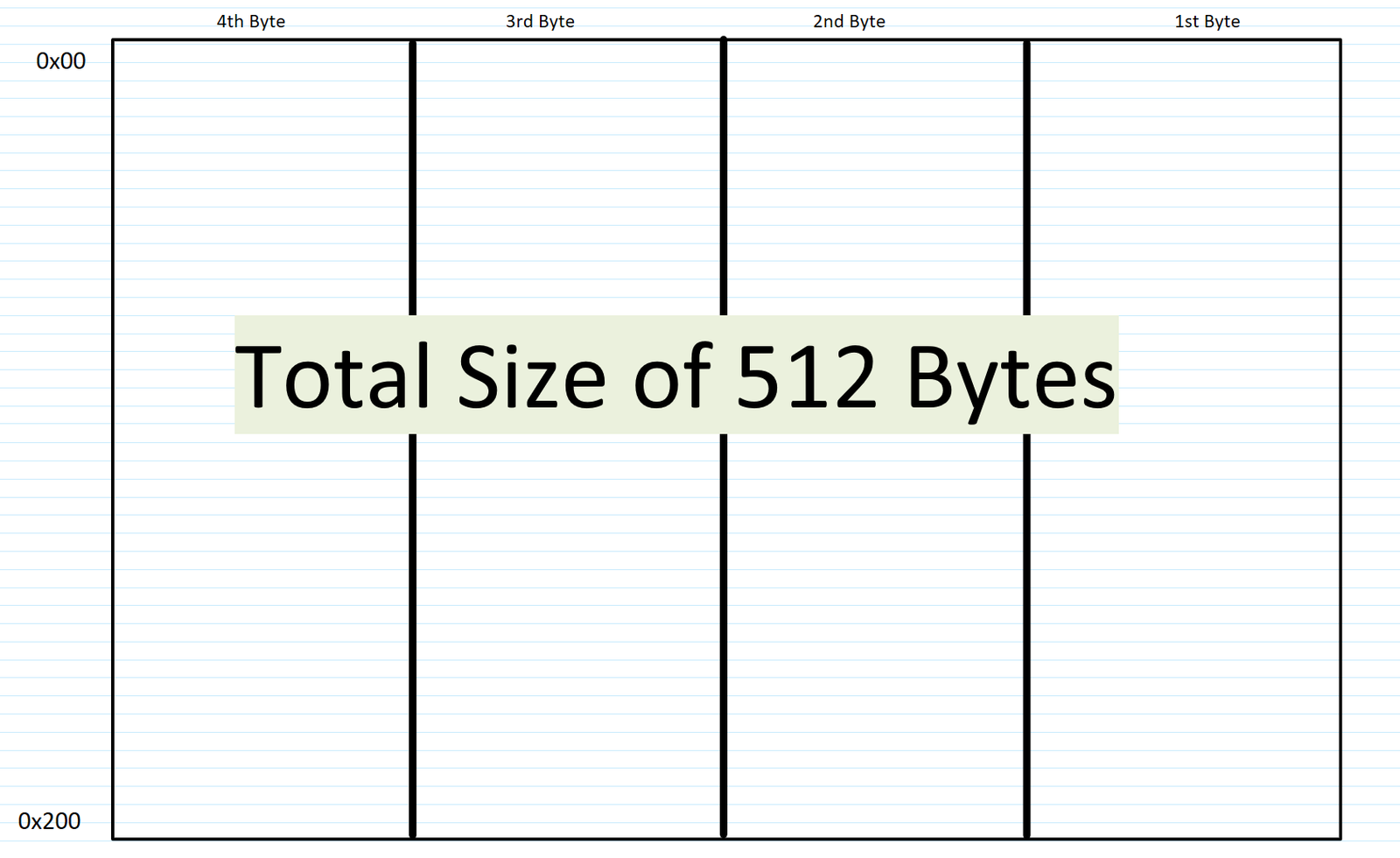
- In FlexCAN module, message buffer space is being termed as Embedded RAM. Both Terms would be used interchangeably throughout the blog.
- FlexCAN peripheral has a fixed Embedded RAM Space which is used to process the CAN data. In S32K1xx Microcontroller’s, the Embedded RAM is of 512 bytes.( Explain for chapter of can peripheral register where address range of message buffer is specified)
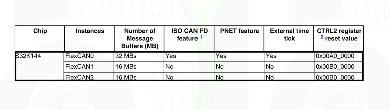
- Each FlexCAN instance in S32K144 MCU has their own Message buffer, but they are of different sizes.( explain from instance feature difference table and then comparing that to above point statement)
FlexCAN instance 0 has 512 bytes and FlexCAN instance 1&2 has 256 bytes of Embedded RAM.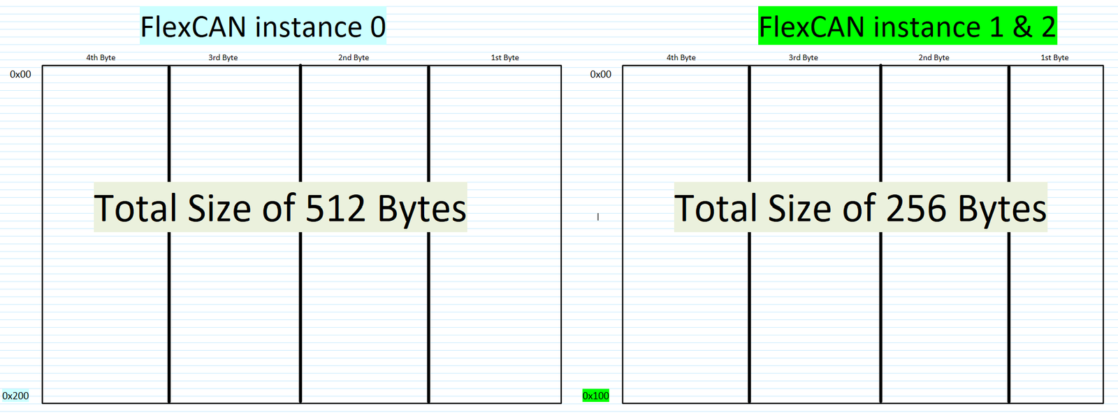
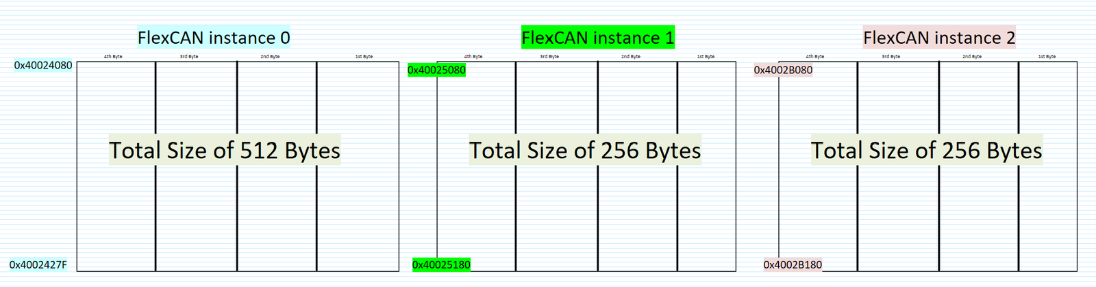
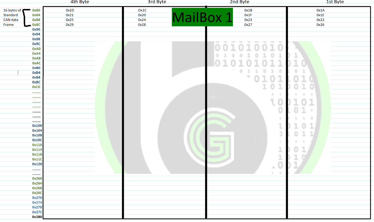
- The Embedded RAM in FlexCAN Peripheral space starts from address of 0x0080 offset of corresponding FlexCAN instance base address. Embedded RAM space is from 0x080-0x280 memory address in case of FlexCAN module 0 and from 0x080-0x180 in case of FlexCAN module 1&2.
For FlexCAN Instance 0 message buffer starts at: 0x40024080, FlexCAN instance 1 message buffer starts at 0x40025080 and for FlexCAN instance 2 message buffer starts at 0x4002B080
- Now if we zoom in to Embedded RAM space, its is divided by offset of 4 bytes. As Shown in figure.
- Further, if we zoom in to write/read on Embedded RAM it has a structure, according to which CAN data frame is written/read into it. It is called Message Buffer Structure. We will get into it in message buffer structure section.
MailBox Mechanism
- If we have Standard CAN frame, in which we are sending 8 bytes of payload data, so according to above message structure it is gonna occupy 16 bytes of space. Starting from first address pace of message buffer: 0x80 till 0x90, first 4 rows would be occupied to write a single CAN data frame. Whether its a Standard CAN frame or Extended CAN frame, its gonna be occupy 16 bytes only.
- If we are using CAN FD, in which we are sending 16 bytes of payload data, so according to above message structure it is gonna occupy 24 bytes of space. Starting from first address pace of message buffer: 0x80 till 0x98, first 6 rows would be occupied to write a single CAN data frame of CAN FD.

- In the case of 512 bytes of Embedded RAM and CAN data size of 16 bytes, we can have total 32 such sections of Embedded RAM. Each Section is termed as mailbox,
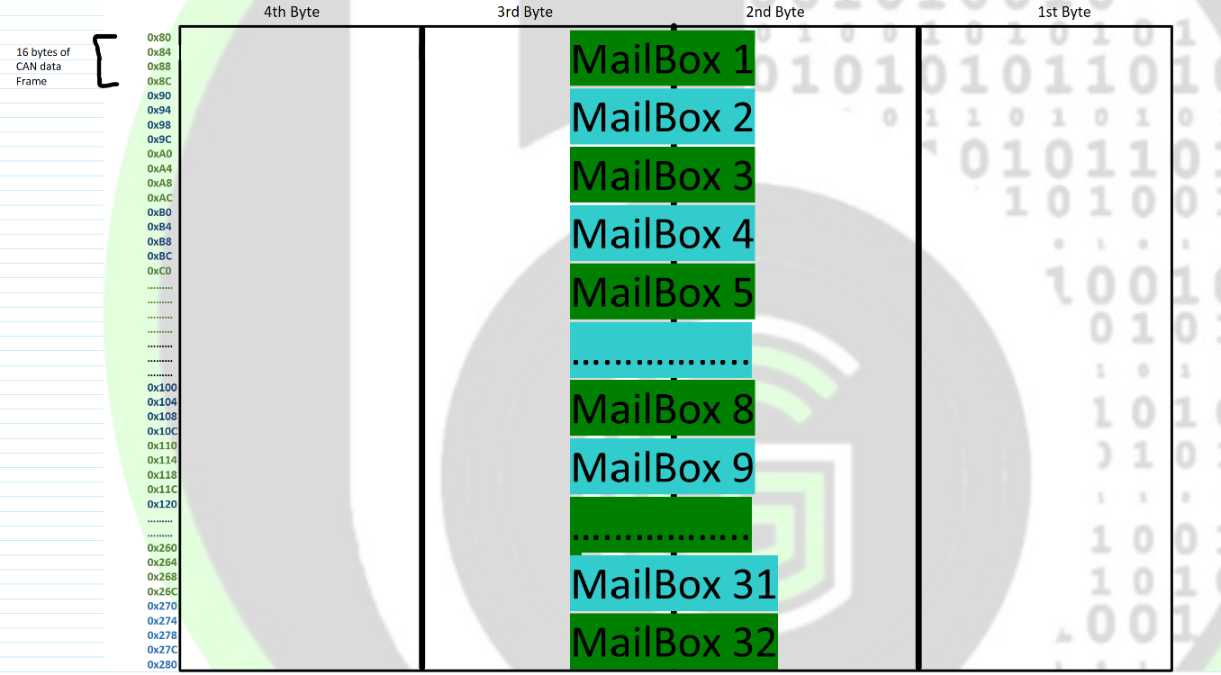
- Each Mailbox can be configured as reception or transmission, all supporting standard and extended messages.
- Number of mailboxes would be different. It would not be 32 everytime. FlexCAN module have flexible mailbox configuration according to CAN data size and instance of FlexCAN that we are using:
- So, in Extended and Standard CAN communication, a single CAN Data Frame will be of 16 bytes. But in the case of CAN-FD a single CAN Data frame can be of 16,24,40 or 72 bytes depending on message payload of 8,16,32 and 64 data bytes. So according to message buffer structure(As Data payload will increase) more memory space of Embedded RAM would be consumed for writing single CAN data frame of higher payloads and so does our total mailbox count will decrease.
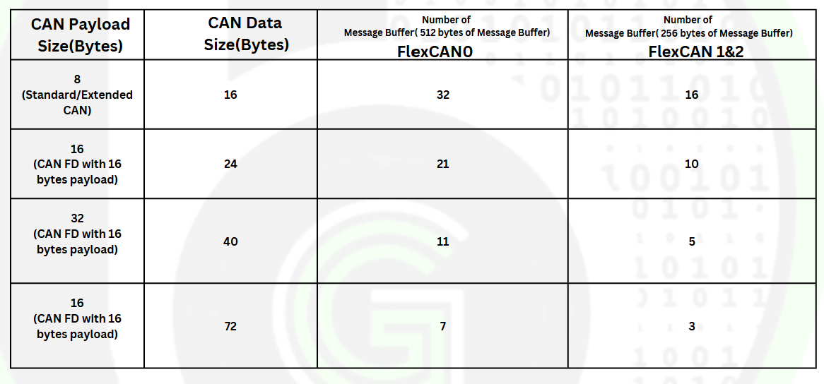
- Also in FlexCAN instance 0, it has message buffer space of 512 bytes so it can fit in 32 mailboxes of 16 bytes CAN frame. In the case of FlexCAN instance 1 & 2, it has message buffer space of 256 bytes so it can fit in only 16 mailboxes. So, mailbox count also varies depending on size of message buffer space.
- Now for better understanding we are going to refer FlexCAN instance 0 and Standard CAN, which occupies 16 bytes of CAN single frame.
- Then as CAN message ID and data is written into address denoted my that mailbox number, a Flag will be set in IFLAG1 FlexCAN peripheral register signifying successful transmission/reception of CAN frame.
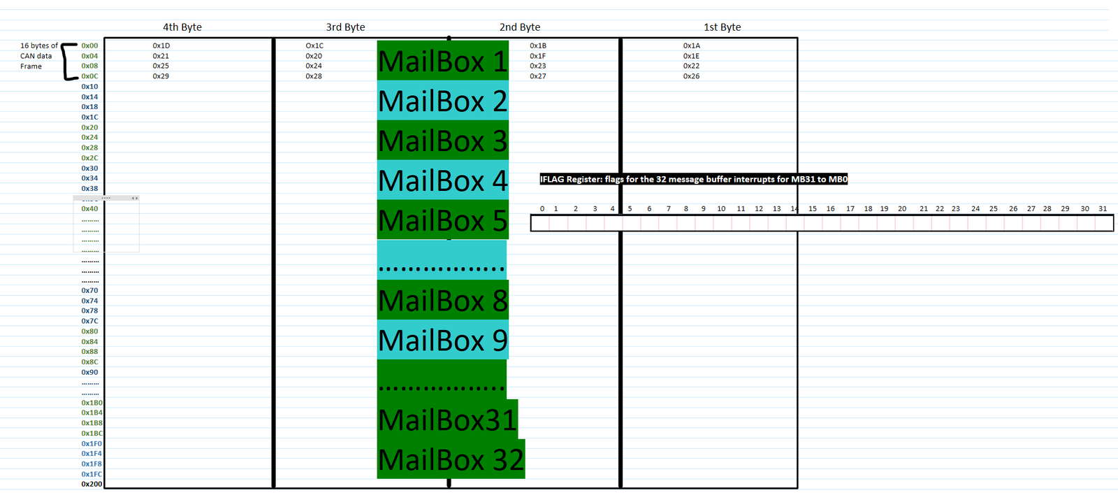
- IFLAG1 register is interrupt status register, which has 32-bit fields. Each bit for one mailbox. So corresponding bits of IFLAG register will be set depending upon mailbox used.
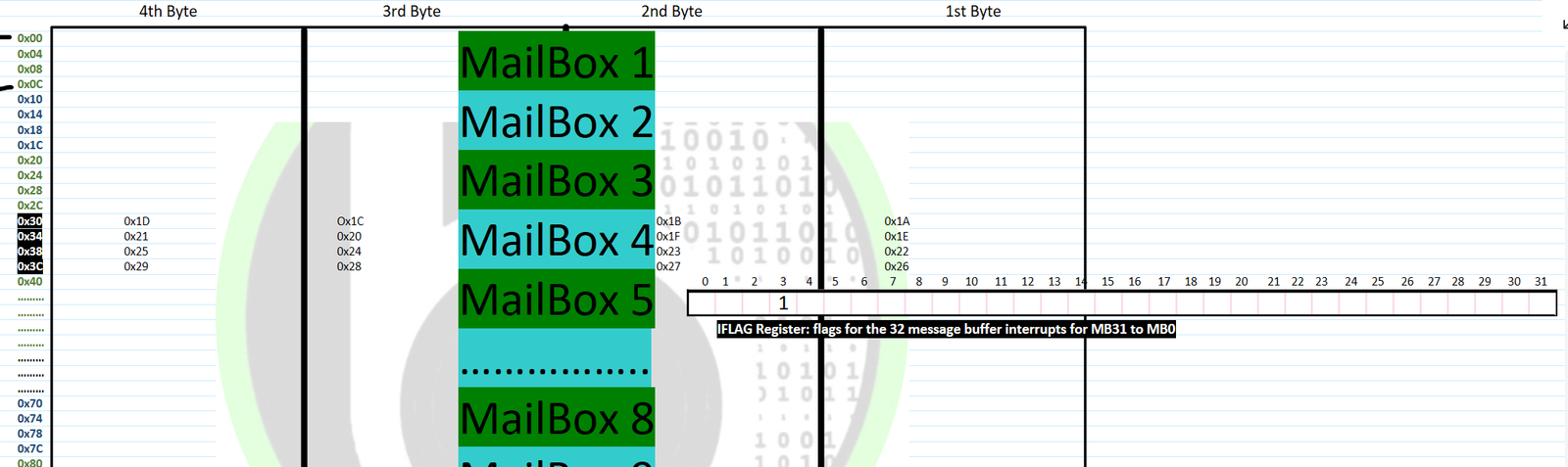
- So if say mailbox 4 is used for transmission of CAN data, in which 0x320 message ID and CAN data of : 0x11, 0x22,0x33 and…. is written. So IFLAG1[4] bit will be set, when Successful CAN transmission is done. Now as mailbox 4 denotes address xyz in case of flexcan_instance 0. So we need to fill corresponding message buffer address space with corresponding contents as per message buffer structure at xyz address. In this case MCU will write CAN message ID and CAN data on the mailbox address space.
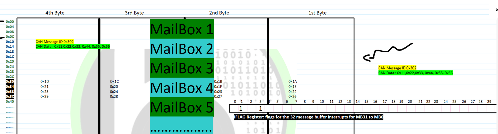
- And say if mailbox 2 is used for reception, which we(MCU) will configure with message ID 0x302. meaning if any CAN message is received by CAN peripheral with message ID 0x300, it will copy its data into the address of mailbox 2. MCU will read the CAN data from this address and on successful reading/receiving IFLAG register bit will be set. The corresponding bit of IFLAG will be set depending on mailbox value.
FIFO Mechanism working
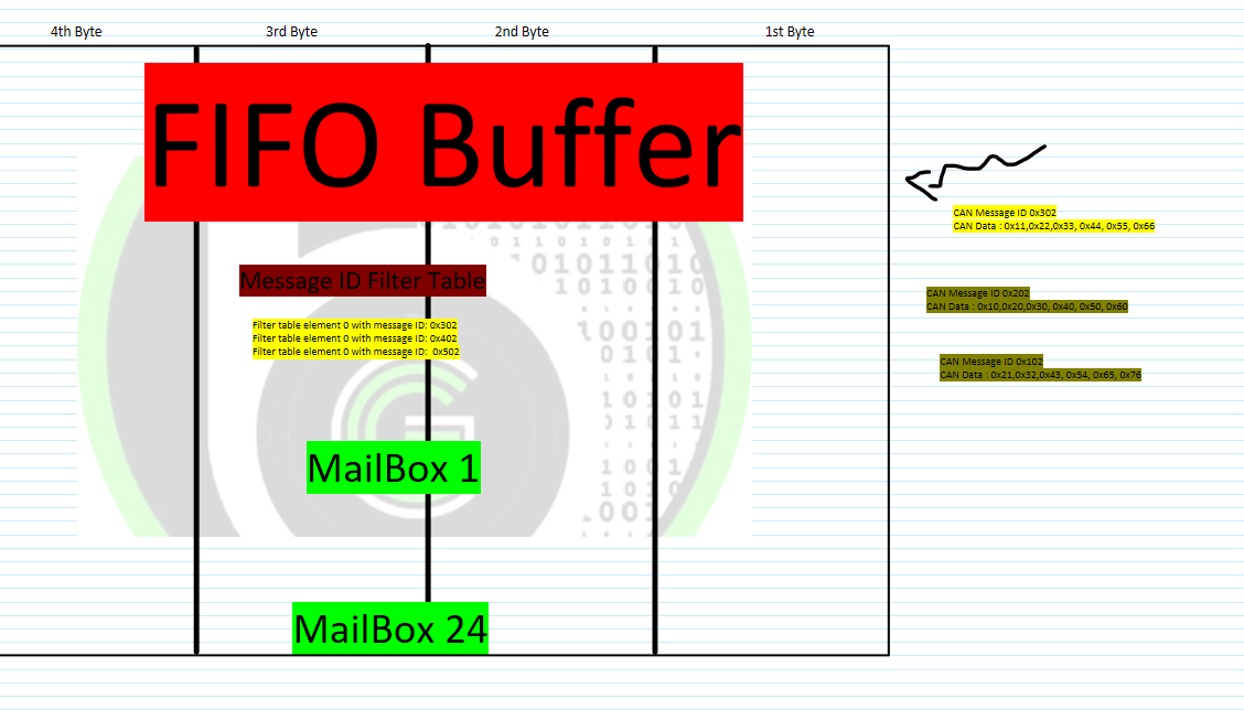
- When we are using FiFo configuration in FlexCAN module, address space 0x80-0xDC of message buffer would be occupied by FiFo Buffer.
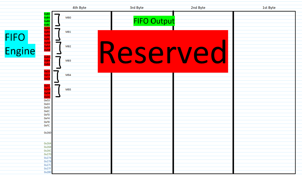
- The reserved area is used for internal use for doing FIFO mechanism and FIFO output/buffer will store the received CAN frame, according to Rx FIFO structure which must be read by CPU as a message buffer.
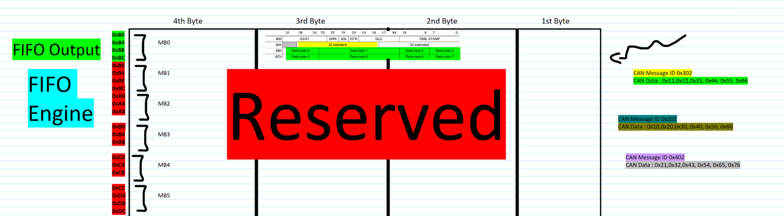
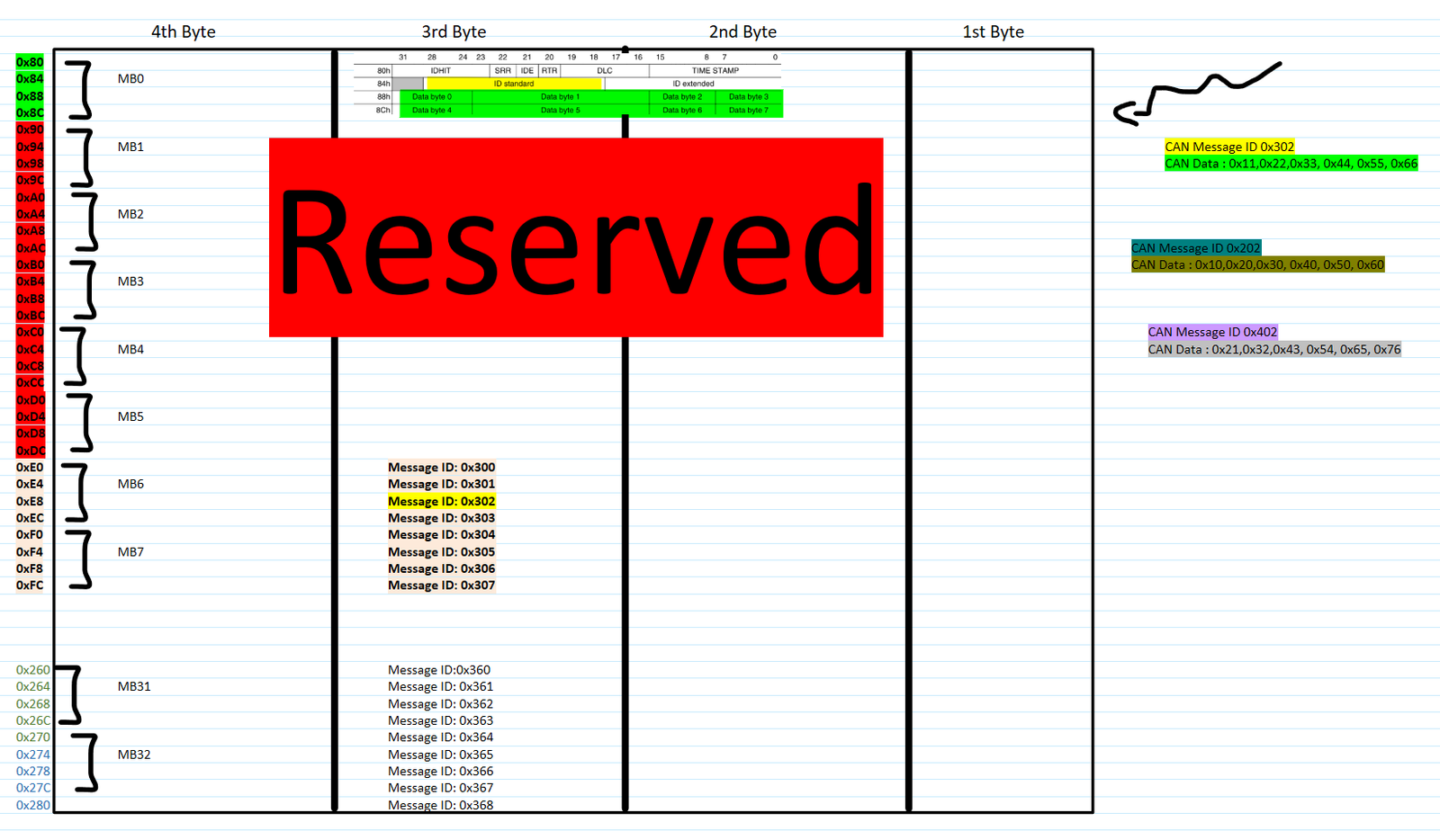
- Now FIFO output is buffer, in which external CAN message Data will be received only if it matches the acceptance criteria in Message ID filter table. Acceptance criteria is based on message ID. If External CAN message ID matches with Message ID mentioned in Message ID filter table, only then FIFO buffer will be filled with corresponding CAN message data.
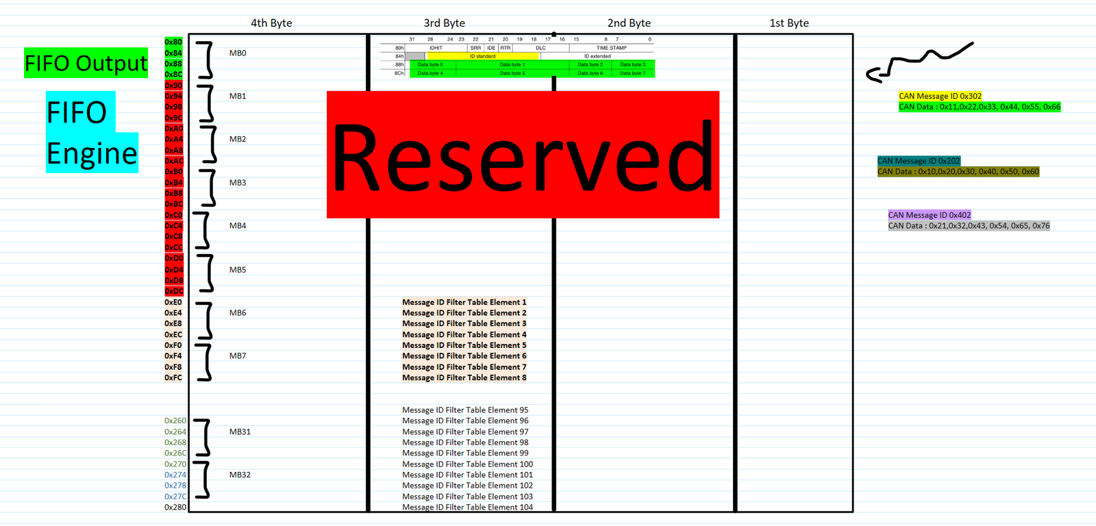
- Now this Message ID filter table is also in message buffer address space only. When FIFO mechanism is enabled, address space from 0xE0 to 0x280 can be used by message ID filter table, in the offset of 4 bytes. In every Message ID filter table element, we can configure which message ID to be accepted.
- This configuration is based on Message ID table structure. More the number of filter elements, a greater number of different CAN messages based on their message ID can be configured to get accepted and received.
- One interesting here to observe is that for doing FIFO mechanism, mailboxes 0-5 are consumed by FIFO engine. And by default, mailboxes 6-7 are used by Message ID filter table. So if we are using FIFO mechanism, number of mailboxes available to us will be decreased.
- Then in order to use mailboxes, we will be able to use number of available mailboxes left after FiFo Consumption. So saw we want to use mailbox 4 further for transmission of CAN data, if FIFO mechanism is being enabled. Then it would show an error, one of the error status bit would be set. As mailbox 4 memory location is being used by FIFO engine. If we use mailbox 9, we can use that as FIFO engine ends at mailbox 5 and Message ID Filter table elements ends at mailbox 7 by default. So when using FIFO for receiving the CAN data, then in that case for transmission we have to make sure that mailbox number which we use is apart from mailboxes which are consumed in FIFO engine and message ID filter table elements.
- Also their are many features in FlexCAN module via which priority of messages to be send with Mailbox can be used. We will be covering those things as we cover the practical experiements.