
FTM has a 16-bit counter that is used by the channels either for input or output modes.
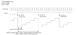
- Up Counting:
Counter counts from x value to y value. X value is starting value of counter and then it increments till y value. CNTIN register defines start value( that is X ) and MOD register defines the final value that is Y.
In Up counting Y>X. QUADEN=0 and CPWMS=0.
FTM period when using up counting is (MOD-CNTIN + 0x0001) x period of counter clock.
Say MOD is 9999 abd CNTIN is 0 and period of counter clock is 10 ms.
So (((9999-0) +1)*.01) = 10 secs.
- Up-down counting:
Co
- Quadrature Decoder Mode:
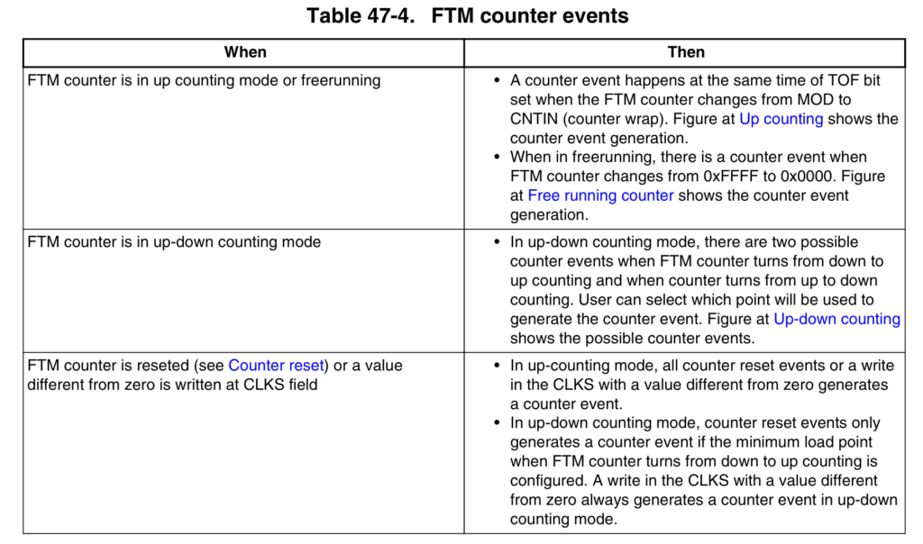
Counter Events
Counter events can be used as reload opportunities to FTM register synchronization
mechanism.
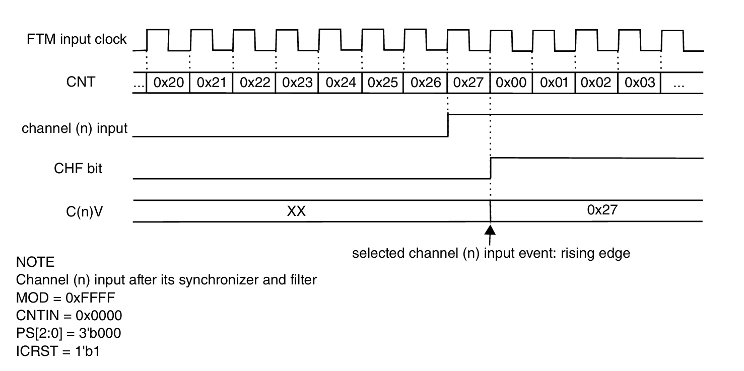
- FTM Input Capture Mode
–> When a selected edge occurs on the channel input, the current value of the FTM counter
is captured into the CnV register, at the same time the CHF bit is set and the channel
interrupt is generated if enabled by CHIE = 1.
Writes to the CnV register are ignored in input capture mode.
If the channel (n) is in input capture mode and CnSC[ICRST = 1], then when the selected
input capture event occurs in the channel (n) input signal, the current value of the FTM
counter is captured into the CnV register, the CHF bit is set, the channel (n) interrupt is
generated (if CHIE = 1) and the FTM counter is reset to the CNTIN register value.
This allows the FTM to measure a period/pulse being applied to the channel (n) input
(number of the FTM input clocks) without having to implement a subtraction calculation
in software subsequent to the event occurring.
- Capture Test Mode
- Dual Edge Capture Mode
- One-Shot Capture Mode
- Continous Capture Mode
- Pulse Width Measurment
- Period Measurment
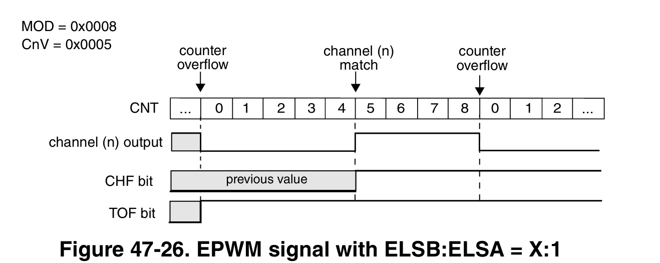
- FTM PWM Mode
- Edge Aligned PWM
This type of PWM signal is called edge-aligned that is Signals are generated with High and Low values repeatdely as counter reaches the set values in CnV and MOD register.
- Center Aligned PWM Mode
- In the CPWM mode, the FTM counter counts up until it reaches MOD and then counts
down until it reaches CNTIN and match. happened when FTM counter = CnV.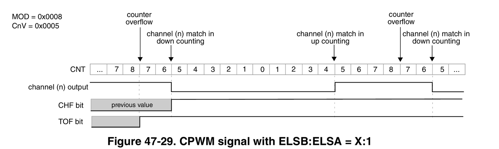
- Combine Mode
In Combine mode, an even channel (n) and adjacent odd channel (n+1) are combined to
generate a PWM signal in the channel (n) output.
The channel (n) CHF bit is set and its interrupt is generated, if channel (n) CHIE = 1, at
the channel (n) match (FTM counter = C(n)V). The channel (n+1) CHF bit is set and its
interrupt is generated, if channel (n+1) CHIE = 1, at the channel (n+1) match (FTM
counter = C(n+1) V).
In this Asymmetrical PWM Mode also comes.
- Modified Combine PWM Mode
The Modified Combine PWM mode is intended to support the generation of PWM
signals where the period is not modified while the signal is being generated, but the duty
cycle will be varied. In this mode, an even channel (n) and adjacent odd channel (n+1)
are combined to generate a PWM signal in the channel (n) output. Thus, the channel (n)
match edge is fixed, and the channel (n+1) match edge can be varied.
In Complementary mode, the channel (n+1) output is the inverse of the channel (n)
output.
The channel (n+1) output is the same as the channel (n) output when:
- channels (n) and (n+1) are on Combine Mode or Modified Combine PWM Mode
The channel (n+1) output is independent from channel (n) output when:
- channel (n) is on Output Compare Mode, EPWM or CPWM
Deadtime insertion
DEADTIME register defines the deadtime delay that can be used for all FTM channels.
The clock for the DEADTIME delay is the FTM input clock divided by DTPS bits, and
the {DTVALEX[3:0], DTVAL[5:0]} bits define the deadtime modulo, that is, the
number of the deadtime prescaler clocks.
The deadtime delay insertion ensures that no two complementary signals (channels (n)
and (n+1)) drive the active state at the same time.
- If POL(n) = 0, POL(n+1) = 0, and the deadtime is enabled, then when the channel (n)
match (FTM counter = C(n)V) occurs, the channel (n) output remains at the low value
until the end of the deadtime delay when the channel (n) output is set. Similarly, when the
channel (n+1) match (FTM counter = C(n+1)V) occurs, the channel (n+1) output remains
at the low value until the end of the deadtime delay when the channel (n+1) output is set.
See the following figures. - If POL(n) = 1, POL(n+1) = 1, and the deadtime is enabled, then when the channel (n)
match (FTM counter = C(n)V) occurs, the channel (n) output remains at the high value
until the end of the deadtime delay when the channel (n) output is cleared. Similarly, when the channel (n+1) match (FTM counter = C(n+1)V) occurs, the channel (n+1)
output remains at the high value until the end of the deadtime delay when the channel (n
+1) output is cleared.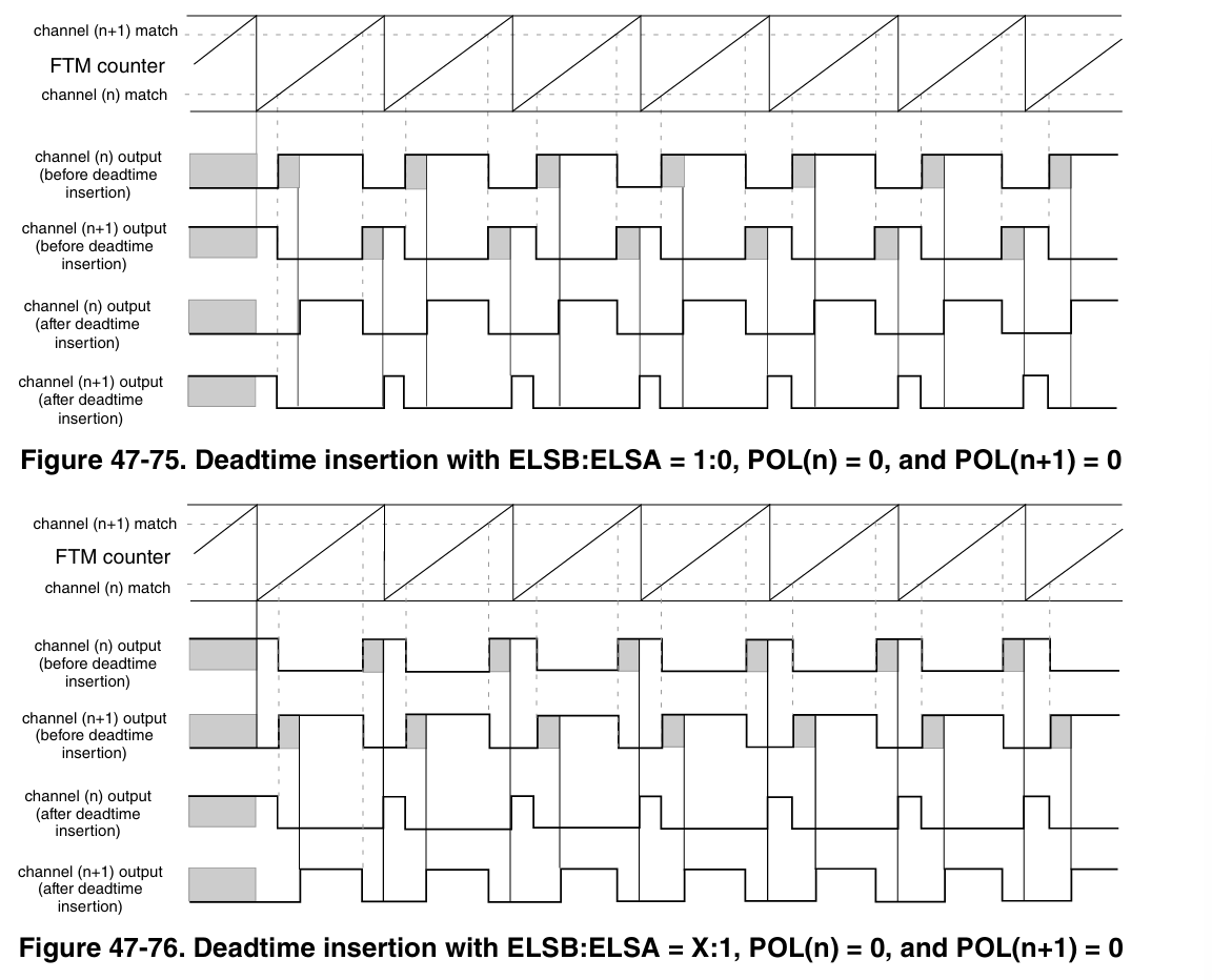
FTM blocks knowledge:
Way of PWM Generation:
- Software Output Control Mode
- Hardware Output Control Mode
The software output control forces the channel output according to software defined
values at a specific time in the PWM generation. The CH(n)OC bit enables the software output control for a specific channel output and
the CH(n)OCV selects the value that is forced to this channel output.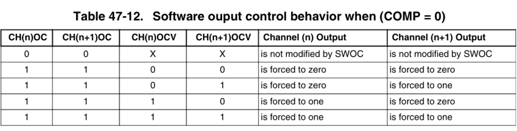
- FTM Clock
- FTM Counter
- FTM deadtime/inverting dithering overview
- FTM Trigger
- FTM faults
- PWM configuration and maths concept