Overview
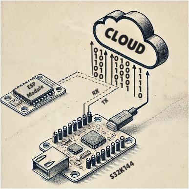
Welcome to another part of Module Interfacing using the AUTOSAR MCAL driver. In this blog, we’ll interface ESP8266 with S32K144 to enable IoT.
What is IoT Enablement ?
–> IoT (Internet of Things) enablement refers to the process of equipping devices, systems, or services with the necessary capabilities to connect to the internet and interact with each other. These “things” can be sensors, appliances, machines, or even cars—anything that can collect, share, and act on data. IoT enablement allows these devices to:
- Gather data from their surroundings or users.
- Communicate that data through the internet.
- Act on insights from received data or user commands.
–> IoT enablement often includes integrating hardware (like sensors), software (like apps or platforms), and network connectivity (like Wi-Fi or cellular). This enables seamless, smart automation and enhances functionality in industries like home automation, healthcare, agriculture, and more.

How ESP Integration Helps in IoT Enablement
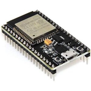
–> ESP microcontrollers like the ESP8266 or ESP32 play a crucial role in IoT projects due to their built-in Wi-Fi and Bluetooth capabilities, which allow them to connect to the internet with ease. This seamless integration with cloud services enables other devices to send and receive data effortlessly, empowering IoT systems via the ESP module.
–> Here’s how ESP enhances IoT integration:
- Simplified Connectivity: The ESP module handles Wi-Fi/Bluetooth communication, eliminating the need for additional modules.
- Cost-Effectiveness: With ESP’s affordable pricing, integrating internet connectivity into IoT systems becomes much cheaper.
- Cloud Communication: ESP modules can easily send data to the cloud, where it’s stored, processed, or used to trigger automated responses.

AT Commands vs. Arduino Programming for IoT with ESP Modules
–> AT commands provide a quick, flexible way to communicate with ESP modules (like ESP8266/ESP32) without needing to write complex firmware. They are particularly useful for beginners or projects that require rapid prototyping. Here’s a concise overview:
- Simple Communication: AT commands are text-based, making tasks like Wi-Fi connections or data transmission easier without heavy coding.
- Cross-Platform: You can send AT commands from different devices (PC, microcontrollers) for versatile IoT setups.
- Faster Setup: No need to load complex firmware—connect to networks or send data quickly using serial commands.
- Low Resource Use: Offloads networking tasks to the ESP, allowing the main controller to focus on other functions.
Key Differences:
| Feature | AT Commands | Arduino Programming |
|---|---|---|
| Ease of Use | Simple, no coding skills needed | Requires knowledge of C/C++ |
| Flexibility | Works across multiple devices/platforms | Platform-dependent firmware |
| Resource Efficiency | Low resource usage on host devices | Host handles network logic, more resources |
| Customization | Limited customization of network functions | Full control over functionality and optimization |
| Setup Speed | Faster prototyping | Slower, requires coding and firmware flashing |
–> AT commands are ideal for quick IoT projects, while normal programming suits advanced, highly-customized solutions.

Getting Started
We are going to move toward the embedded software understanding of UART configuration(remember that peripheral module in S32K144 is LPUART stands for Low-Power UART, therefore we’ll be referencing UART as LPUART), as per requirement, under the AUTOSAR MCAL standards, according to our DIY project statement. Make sure to follow the steps keenly and if any suggestion is invoked, please submit it on our community forum.
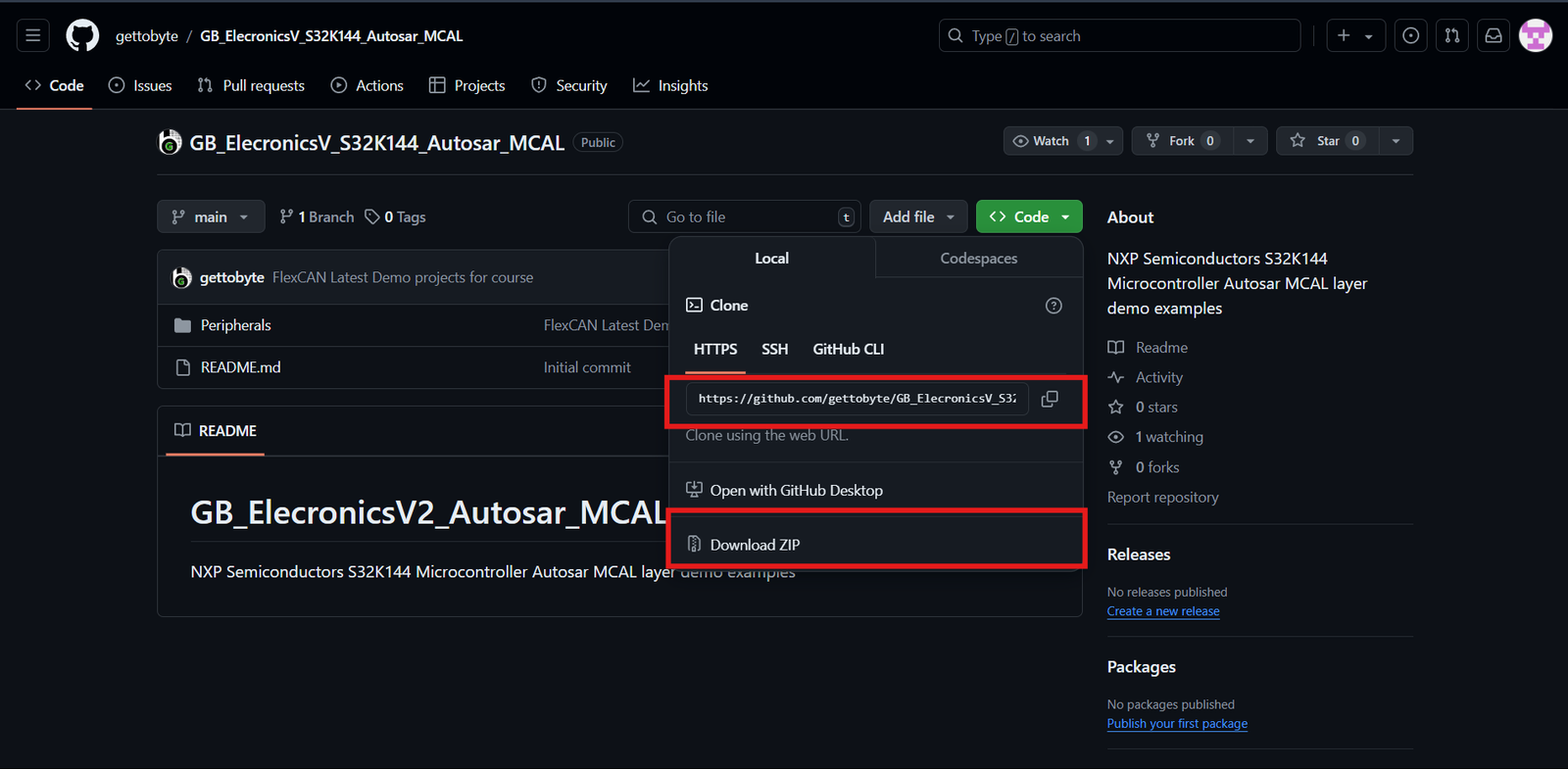
Step 1: Cloning the Repo from our GettoByte Github
–> Download the ElecronicsV board Demo codes from the GitHub Repo of Gettobyte Technologies. If you have installed the Git, then one can clone the repo. Otherwise, one can download the repo by its zip file.
–> For cloning the repo, you can directly download it as a .zip file and extract it, else you can also use Tortoise Git to extract the files.

Step 2: Opening the cloned repo in S32 Design Studio
–> After getting the repo, now we are going to open the GitHub repo Example projects in S32 Design Studio. Make sure that you have downloaded the S32 Design Studio 3.4 and S32K1 RTD package versions 1.0.0 and 1.0.1 which we have stated in the tools installation.
–> Note: Every Demo Project have their infividual Branch in Git Repository. Therefor, you should always select correct branch to run correct Demo.
–> Follow the below steps mentioned in slider to Open the Example projects in S32 Design Studio.
Code and Explanation
Breaking down the code
					/* Including necessary configuration files. */
#include "Mcal.h"
#include "Mcu.h"
#include "Port.h"
#include "Uart.h"
#include "Platform.h"
#include "Lpuart_Uart_Ip_Irq.h"
#include "ESP8266_ThingSpeak.h"
- Declaration of important and used header files where
- “Mcal.h” is the header for MCAL standards
- “Mcu.h” is the header for Clock configuration.
- “Port.h” is the header for Pins and Port configuration.
- “Uart.h” is the header for UART configuration.
- “Platform.h” is the header for InterruptHandler
- “Lpuart_Uart_Ip_Irq.h” is the header for LPUART ISR Declaration.
- “ESP8266_ThingSpeak.h” is the custom header for ESP8266 to ThingSpeak conncetion.
extern void LPUART_UART_IP_0_IRQHandler(void);
2. External inclusion of IRQHandler for main.c usage purposes
					uint16_t pwm_duty_cycle(uint8_t duty_cycle_percent)
{

	uint16_t duty_cycle = ((32768 * duty_cycle_percent)/100);

	return (duty_cycle);

}
3. Function prototyping for an input to percentage duty cycle conversion.
					void mcu_init();

void mcu_init(void)
{

	/*-------------------Clock_Configuration via MCU Peripheral---------------*/

	Std_ReturnType Mcu_Status;
	Mcu_Init(&Mcu_Config_BOARD_InitPeripherals);

	Mcu_Status = Mcu_InitClock(McuClockSettingConfig_0);

	#if (MCU_NO_PLL == STD_OFF)

		while ( MCU_PLL_LOCKED != Mcu_GetPllStatus() )
		{
			/* Busy wait until the System PLL is locked */
		}

		Mcu_DistributePllClock();
	#endif

	Mcu_SetMode(McuModeSettingConf_0);

	Mcu_Init(&Mcu_Config_BOARD_InitPeripherals);

	/*------------------------------------------------------------------------*/

}
4. Function for clock configuration and initialization to CPU and different peripherals.
					void port_init();

void port_init(void)
{

	/*-------------------------------Port Configuration-----------------------*/

		Port_Init(NULL_PTR);

	/*------------------------------------------------------------------------*/

}
5. Function for MCU Port initialization, without this function pins of the microcontroller will be settled for usage.
					void irq_init();

void irq_init(void)
{

	/*----------------------------Platform Configuration----------------------*/

	    /* Initialize IRQs */
	    Platform_Init(NULL_PTR);
	    Platform_InstallIrqHandler(LPUART0_RxTx_IRQn, LPUART_UART_IP_0_IRQHandler, NULL_PTR);

	/*------------------------------------------------------------------------*/

}
6. Function for IRQ_Handler initialization where the passed parameter is the structure of defined requirements in the .mex file.
AT_init();
7. Function for initializing LPUART peripheral and loading its desired parameter into the register.
AT_receiveResponse();
8. Function for starting the LPUART reception via interrupt
AT_reset();
9. Function for sending the reset AT command to ESP Module.
AT_set_WiFiMODE();
10. The function of this AT command is to get the value scope of WiFi mode, including station mode,
softAP mode, and station+softAP mode.
AT_connectWiFi();
11. The function of this AT command is to connect the ESP Module to user required WiFi connection.These WiFi credentials can be modified in the S_M Driver folder which contains header files.
AT_singleConnection();
12. The function of this AT command is to select whether you want multiple connections or single connections using the ESP Module.
AT_connect_ThingSpeak();
13. The function of this AT command is to configure the type of connection(like TCP, UDP, or SSL), IP addresses to which the connection is established, and Port Number.
AT_sendData(91);
13. The function of this AT command is to send data over the internet to a connected IP address. Parameter to be passed should always be “int”.
Conclusion
In this blog, we learned how an ESP Module is used for IoT purposes where a simple AT command and UART connection can make any microcontroller have internet accessibility. These modules can also help in Cloud Services and Logging.
Similarly, you can follow more sensor and module interface blogs for learning through practical implementation.