Overview
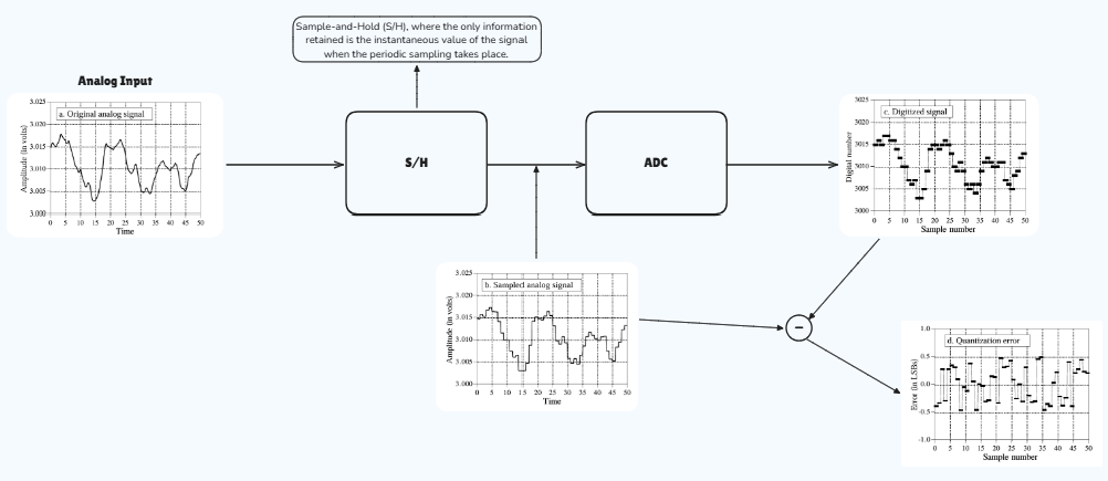
Welcome to Module Interfacing using AUTOSAR MCAL driver. In this blog, we’ll learn how to enable ADC peripherals using MCAL Driver. ADC peripherals in S32K144 have a very great range of operations but we’ll discuss some basic ones, for advanced control you can anytime go to our course and learn in detail.
What and Why is ADC?
–> ADC (Analog-to-Digital Converter) is a critical peripheral in embedded systems that converts an analog (continuous) signal into a digital (discrete) signal. This allows microcontrollers and processors operating in the digital domain to input and process real-world analog inputs like temperature, sound, light intensity, or pressure.
Key Measurements in ADC
Resolution: The number of bits (e.g., 8-bit, 10-bit, 12-bit) used to represent the analog input.
Sampling Rate: The frequency at which the ADC samples the analog input, measured in samples per second.
Reference Voltage (Vref): The maximum voltage level the ADC can measure.
Table of Concise Explanation
| ADC Parameter | Measurement | Purpose | Effect of Change |
|---|---|---|---|
| Resolution | Bits | Precision of conversion | Higher resolution = more accurate |
| Sampling Rate | Samples per second | Speed of measurement | Higher rate = better for fast signals |
| Reference Voltage | Max input voltage level | Defines sensitivity range | Lower Vref = finer low-range sensitivity |
Why ADC is Essential in Embedded Systems
ADCs bridge analog signals with digital processing, allowing real-world data integration into digital systems. By adjusting its key parameters—resolution, sampling rate, and reference voltage—the ADC enables optimal signal representation, empowering precise control and monitoring applications in everything from industrial automation to consumer electronics.

Getting Started
We are going to move toward the embedded software understanding of PWM frequency and duty cycle modulation, as per requirement, under the AUTOSAR MCAL standards, according to our DIY project statement. Make sure to follow the steps keenly and if any suggestion is invoked, please submit it on our community forum.
Step 1: Cloning the Repo from our GettoByte Github
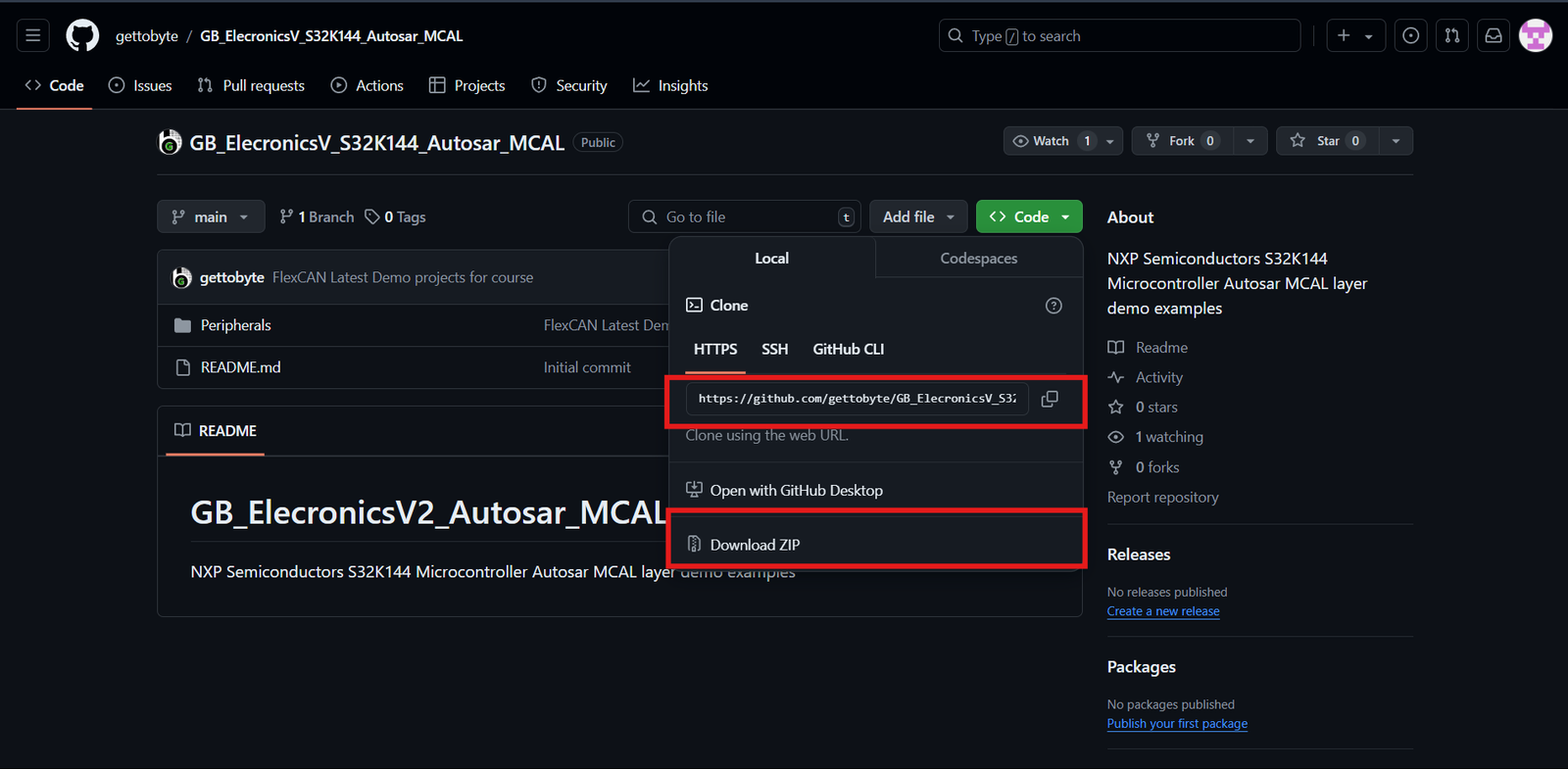
Download the ElecronicsV board Demo codes from the GitHub Repo of Gettobyte Technologies. If you have installed the Git, then one can clone the repo. Otherwise, one can download the repo by its zip file.
For cloning the repo, you can directly download it as a .zip file and extract it, else you can also use Tortoise Git to extract the files.

Step 2: Opening the cloned repo in S32 Design Studio
After getting the repo, now we are going to open the GitHub repo Example projects in S32 Design Studio. Make sure that you have downloaded the S32 Design Studio 3.4 and S32K1 RTD package versions 1.0.0 and 1.0.1 which we have stated in the tools installation.
Follow the below steps mentioned in slider to Open the Example projects in S32 Design Studio.
Step 3: Building the specific code
In Project Explorer, you can see all the files generated and included for the project but our main focus is on the .mex file which contains all portions of peripheral and MCU-related information. You can directly debug and run the code through the debug option.
To understand the complete explanation of the .mex file and how these different peripherals have different parameters thorough which we can generate our required result, you can follow the details on the courses link mentioned.
Code and Explanation
Breaking down the code
					#include "Mcal.h"
#include "Platform.h"
#include "Clock_Ip.h"
#include "Port.h"
#include "Adc.h"
- Declaration of important and used header files where
- “Mcal.h” is the header for MCAL standards
- “Platform.h” is the header for InterruptHandler.
- “Clock_Ip.h” is the header for Clock configuration.
- “Port.h” is the header for Pins and Port configuration.
- “Adc.h” is the header for ADC configuration.
					void TestDelay(uint32 delay);
void TestDelay(uint32 delay)
{
   static volatile uint32 DelayTimer = 0;
   while(DelayTimer<delay)
   {
       DelayTimer++;
   }
   DelayTimer = 0;
}
2. Function prototyping for a delay function that counts the parameter and decrementing it.
					void IoHwAb_AdcNotification_0( void )
{

	Std_ReturnType StdReturn ;
   	StdReturn = Adc_ReadGroup(AdcGroup_0_WI_OS_PDB_B2B, Result);

}
3. Notification declaration for CallBack Function.
Note: Here, we are reading the converted and stored values of ADC in their respective register. If you don’t read the ADC value from its respective register then it’s gonna hold the initial ADC conversion value and won’t get updated.
					/*************Clock Configuration for MCU**************************/
	Clock_Ip_StatusType clockStatus;
	clockStatus = Clock_Ip_Init(&Mcu_aClockConfigPB_BOARD_InitPeripherals[0]);
	while (clockStatus != CLOCK_IP_SUCCESS)
	{
		clockStatus = Clock_Ip_Init(&Mcu_aClockConfigPB_BOARD_InitPeripherals[0]);
	}
	/* Busy wait until the System PLL is locked */
	while (CLOCK_IP_PLL_LOCKED != Clock_Ip_GetPllStatus());
	Clock_Ip_DistributePll();
	/*******************************************************************/
4. Function for clock configuration and initialization to CPU and different peripherals.
						/* Initialize Platform Driver */
	Platform_Init(NULL_PTR);
	Platform_InstallIrqHandler(ADC0_IRQn, Adc_0_Isr, NULL_PTR);
	Platform_SetIrq(ADC0_IRQn, TRUE);
5. This section is for enabling and configuring the ISR with InterruptHandler. At last InterruptHandler is set to true meaning the enable of that specific mentioned IRQHandler
					/* Initialize all pins using the Port driver */
	Port_Init(NULL_PTR);
6. Function for MCU Port initialization, without this function pins of the microcontroller will be settled for usage.
Adc_Init(&Adc_Config_BOARD_INITPERIPHERALS);
7. Function for ADC initialization where the passed parameter is the structure of defined requirements in the .mex file.
					Adc_CalibrationStatusType CalibStatus;
        Adc_Calibrate(AdcHwUnit_0, &CalibStatus);
        while(CalibStatus.Adc_UnitSelfTestStatus == E_NOT_OK)
        {
        	Adc_Calibrate(AdcHwUnit_0, &CalibStatus);
        }
8. Function for ADC Calibration, improves ADC accuracy by compensating for offset and gain errors, ensuring the digital output accurately reflects the analog input.
					        Adc_SetupResultBuffer( AdcGroup_0_WI_OS_PDB_B2B, ResultBuffer);

        Adc_EnableGroupNotification(AdcGroup_0_WI_OS_PDB_B2B);
9. Adc_SetupresultBuffer() sets the memory buffer to store conversions, whereas Adc_EnableGroupNotification() enable callback function.
					    	Adc_StartGroupConversion(AdcGroup_0_WI_OS_PDB_B2B);

        /*wait until the convertion is done*/
        while( Adc_GetGroupStatus( AdcGroup_0_WI_OS_PDB_B2B ) == ADC_BUSY );

    	TestDelay(200000);
10. This is the main loop consisting of SW_Trigger( of ADC conversion which means that ADC conversions only take place when this API is called. This is a classic example of SW_Triggered ADC.
Conclusion
In this blog, we learned how an ADC SW_Triggered Operation works and functional code explanation. You can make multiple interconnections for different triggering, but those parts are included in our detailed courses. You can always explore yourselves things and ask your doubts in the community forum.
Similarly, you can follow more peripheral interface blogs for learning through practical implementation.